Method and apparatus for cooling a portable computer

a portable computer and circuit device technology, applied in the direction of electrical apparatus casings/cabinets/drawers, instruments, semiconductor/solid-state device details, etc., can solve the problems of reducing the capability of the system, the value of the system in the eyes of consumers, and the inability to meet the requirements of portable computers. to achieve the effect of convenient cooling

Inactive Publication Date: 2005-12-22
PC COMA LLC
View PDF23 Cites 10 Cited by
  • Summary
  • Abstract
  • Description
  • Claims
  • Application Information

AI Technical Summary

Benefits of technology

[0047] The present invention provides a number of technical advantages. One such technical advantage results from the provision within a portable computer of a low-profile cooling assembly for a circuit component such as the processor. In one advantageous configuration, the cooling assembly effects a forced flow of air drawn from externally of the housing, and the air flow from this cooling assembly is routed within the housing to facilitate cooling of other heat-dissipating components. The routing of this air flow is facilitated by techniques which include selection of the number of discharge ports through which the air flow exits the housing, and selection of the location and / or effective size of each such discharge port. The routing of the air flow can also be facilitated by the use of strategically placed vanes within the housing.
[0048] A related advantage is realized where a component has a local finned heat sink in order to facilitate the efficient transfer of heat from that component to the air flow which is traveling from the cooling assembly to a discharge port. Still another advantage is realized where a heat pipe is provided within the housing to help transfer heat, for example from a heat dissipating component to the cooling assembly. Through use of such techniques, a portable computer can be relatively thin and lightweight, and can have a processor which operates at its highest rated speed, while enjoying efficient cooling through use of a configuration that consumes minimal power.

Problems solved by technology

However, operating the processor at a speed less than its maximum rated speed decreases the capability of the system, and thus the value of the system in the eyes of consumers, which is undesirable.
However, while these cooling arrangements have been generally satisfactory for use in desktop computers, they are not entirely satisfactory for use in portable computers.
But an increase in the weight and / or thickness of a portable computer is undesirable from a commercial perspective, because it runs contrary to consumer preference for thin and lightweight units.
The powerful fans used in many desktop cooling arrangements would tend to consume a significant amount of battery power if used in a portable computer, and would thus undesirably shorten the effective battery life.
Although a larger battery could be used, this would result in an increase in the size and / or weight of the portable computer, which as discussed above is undesirable.
Some prior attempts have been made to provide effective cooling in portable computers, but the results have not been entirely satisfactory.
For example, heat pipes have been used to conduct heat from an interior component to an external finned heat sink, but the heat sink adds undesirable weight.
Although the additional weight can be reduced to some extent by making the heat sink from a lightweight material such as magnesium, magnesium is relatively expensive, and the added expense is undesirable.
However, this approach provides only limited benefit, and technology is reaching a point where this type of natural convection cooling is simply inadequate to remove the amount of heat that is being generated.

Method used


Image

  • Method and apparatus for cooling a portable computer
  • Method and apparatus for cooling a portable computer
  • Method and apparatus for cooling a portable computer

Examples


Embodiment Construction

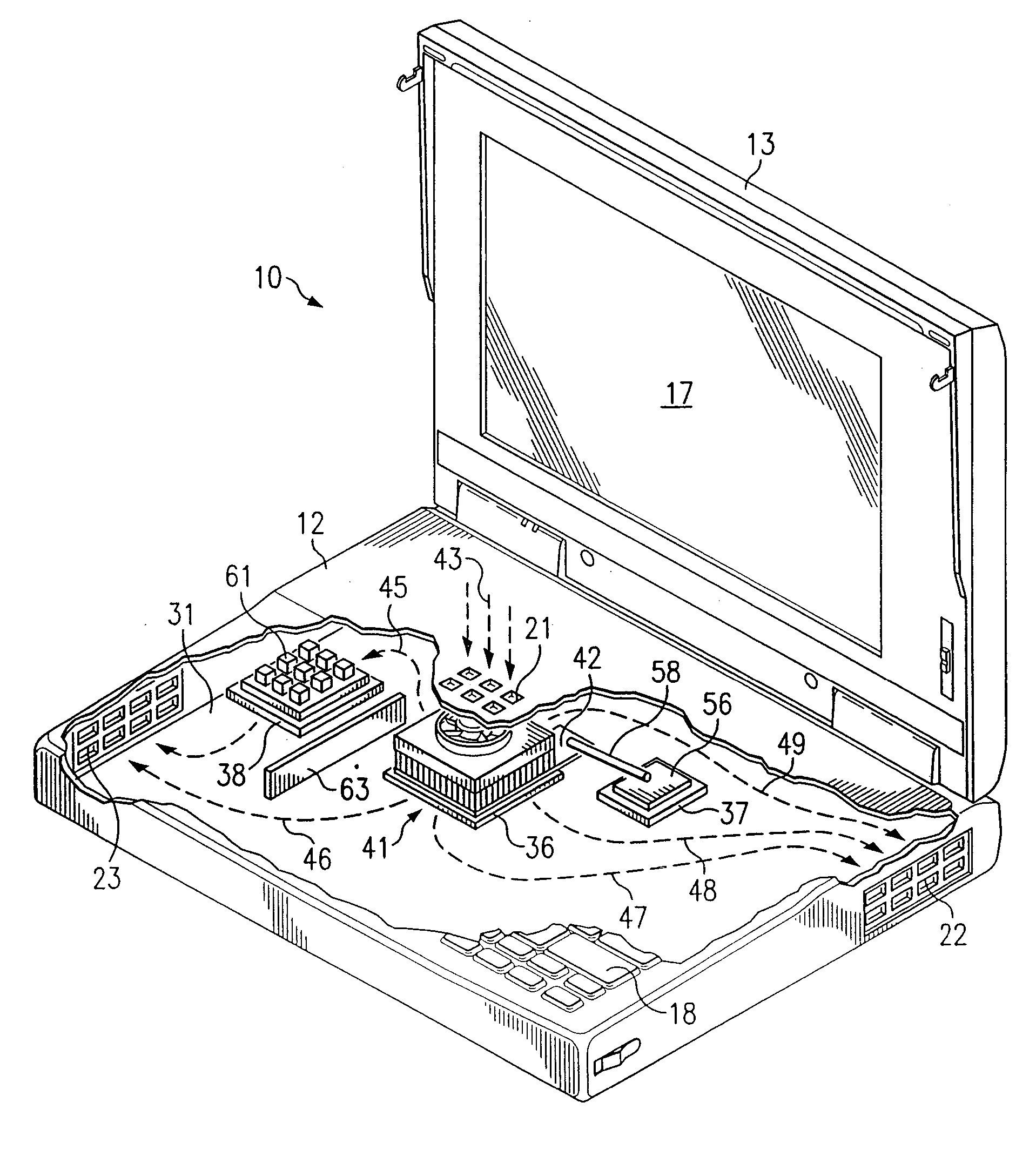
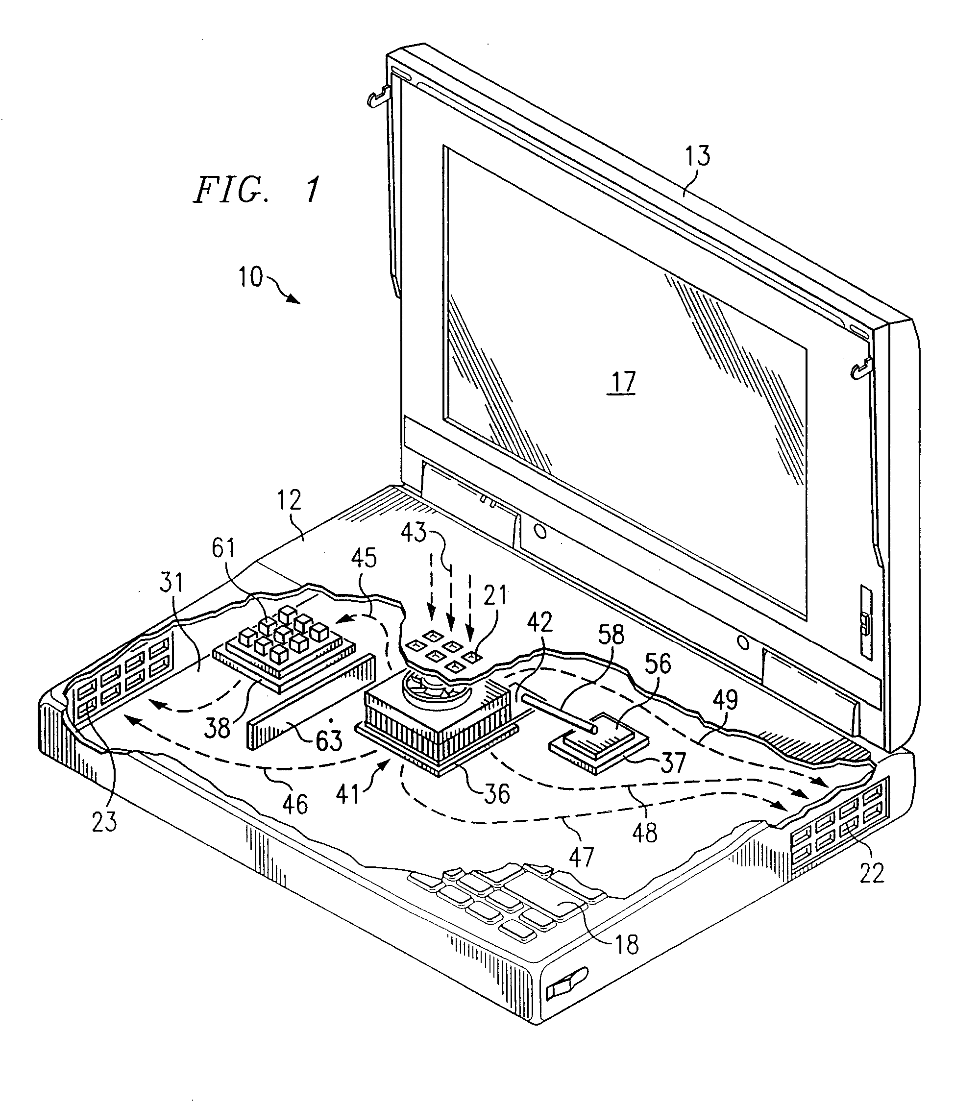
[0017]FIG. 1 is a diagrammatic fragmentary perspective view of an apparatus which is a portable computer 10, and which embodies aspects of the present invention. The computer 10 includes a housing 12 and a lid 13. The lid 13 is pivotally supported on the housing 12 for movement between an open position which is shown in FIG. 1, and a closed position in which the lid is adjacent the top surface of the housing 12. The lid 13 contains a liquid crystal display (LCD) panel 17 of a type commonly used in portable computers.

[0018] A plurality of manually operable keys 18 are provided on top of the housing 12, and collectively define a computer keyboard. In the disclosed embodiment, the keyboard conforms to an industry-standard configuration, but it could alternatively have some other configuration. The top wall of the housing 12 has, in a central portion thereof, a cluster of openings 21 which each extend through the top wall. The openings 21 collectively serve as an intake port. The housi...


PUM


Abstract

A portable computer includes a housing containing a circuit component, and a temperature adjusting arrangement which has a thermally conductive section with a side facing approximately along an axis and thermally coupled to the component. A fluid supply section directs a fluid flow along the axis and the thermally conductive section splits the fluid flow into a plurality of flow portions which each flow through the thermally conductive section in a direction approximately parallel to a plane perpendicular to the axis, the flow portions exiting the thermally conductive section at a plurality of respective locations disposed along a substantial portion of the periphery of the thermally conductive section.

Description

TECHNICAL FIELD OF THE INVENTION [0001] This invention relates in general to techniques for cooling circuit devices and, more particularly, to techniques for cooling circuit devices disposed within a portable computer. BACKGROUND OF THE INVENTION [0002] Over the past fifteen years, personal computers have enjoyed a progressively increasing popularity, including portable computers of the type commonly known as “laptop” and “notebook” computers. During this same time period, significant advances have been made in the design of the processors used in personal computers, including portable computers. In this regard, the amount of circuitry which can be fabricated in a given area of an integrated circuit has increased significantly, thereby facilitating the implementation and fabrication of significantly more sophisticated processor designs. Further, the operational capabilities of processors have increased dramatically, and there have also been significant increases in the speed at whic...

Claims


Application Information

Patent Timeline
Patent Type & Authority Applications(United States)
IPC IPC(8): G06F1/20H01L23/367H01L23/467
CPCG06F1/203H01L23/3672H01L23/467H01L2924/0002H01L2924/00
Inventor WYATT, WILLIAM GERALDSCHWARTZ, GARY J.
Owner PC COMA LLC
Why Eureka
Try Eureka