
Active vibration control in computed tomography systems

a computed tomography and vibration control technology, applied in the field of vibration control in computed tomography systems, can solve problems such as distortion of images, difficulty, and difficulty, and achieve undesirable vibration and distortion of images obtained

Inactive Publication Date: 2005-12-22
GENERAL ELECTRIC CO
View PDF5 Cites 40 Cited by
  • Summary
  • Abstract
  • Description
  • Claims
  • Application Information

AI Technical Summary

Benefits of technology

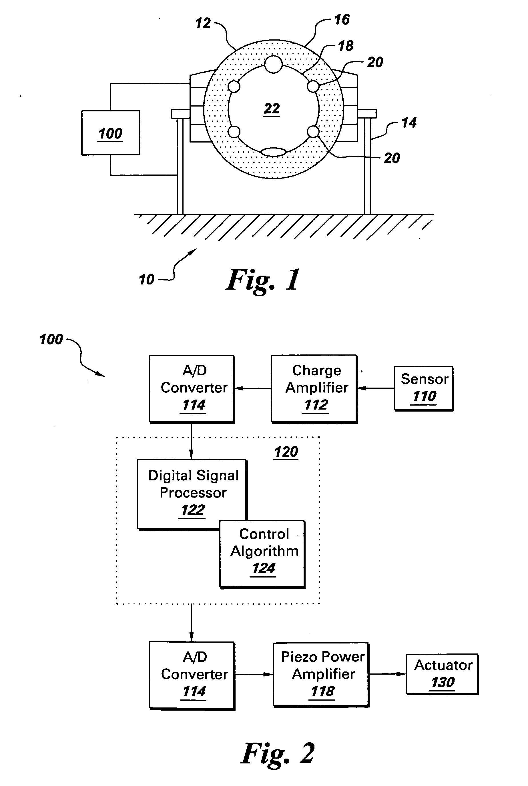
[0008] Briefly, in accordance with an embodiment of the invention, an apparatus for active vibration control of resonance vibrations in a computed tomography (CT) system is provided. The apparatus comprises a sensor coupled to a support frame of the CT system. The sensor detects resonance vibrations signals in the supp

Problems solved by technology

However, there exist multiple sources causing a relative motion between the patient and the gantry geometric center, which include i) irregularity of the bearing and rotating gantry geometry, ii) static and dynamic unbalances of rotating parts mounted on the rotating gantry and iii) occurrence of resonance when rotating harmonics of the gantry coincide with the supporting frame natural frequency.
However, mechanical excitations induced by resonance vibrations can distort the image and present a challenge.
This resonance of the CT frame natural frequency (or one of its harmonics) with the rotating frequency of the gantry leads to undesirable vibrations and distortion in the images obtained.
However, the damping approach is only suitable for higher order frequencies, such as over 100 Hz, and hence cannot be applied to most CT systems.
Given the massive nature of the CT systems, an auxiliary system as a tunable vibration absorber will itself need to be massive, and is hence, impractical.

Method used


Image

  • Active vibration control in computed tomography systems
  • Active vibration control in computed tomography systems
  • Active vibration control in computed tomography systems

Examples


Embodiment Construction

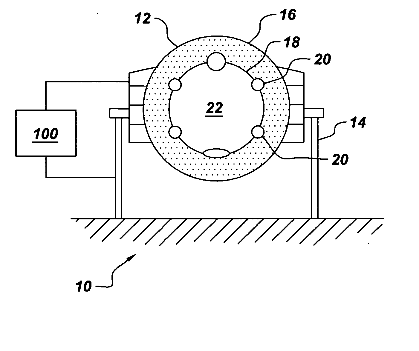
[0012]FIG. 1 is illustrates a CT system 10, having a gantry 12 mounted over a support frame 14, which is coupled to an active vibration control apparatus 100. The gantry is functional to expose a volume to radiation for imaging. The gantry typically includes a stationary base 16 mounted on the support frame, and a rotating base 18 is positioned inside the stationary base. Wherever used, the term “rotating gantry” will be understood to refer to the rotating base of the gantry. Further, the “geometric center” of the gantry is understood to refer to the geometric center of the radiation source and detector elements, and in most cases is the geometric center of the rotating base. The rotating base is mounted with various functional components 20 of the CT system, such as an X-ray source(s), detector array(s), computer modules, among others. These components can be viewed as masses lumped to the rotating base. The imaging volume 22 inside the rotating base is suitable for positioning an ...


PUM


Abstract

An apparatus for active vibration is provided for control of resonance vibrations in a computed tomography (CT) system. The apparatus comprises a sensor coupled to a support frame of the CT system for detecting resonance vibrations and and convert the vibration signal to a corresponding electrical signal. The apparatus further comprises a control device coupled to the sensor for implementing a control algorithm to process the electrical signal to generate a corresponding control signal, which is used for counteracting the resonance vibrations in the support frame.

Description

BACKGROUND OF THE INVENTION [0001] The invention generally relates to computed tomography (CT) systems, and more specifically to vibration control in CT systems. [0002] Generally, conventional CT systems comprise a rotating gantry, and functioning components such as an X-ray source and a detector are typically mounted on the rotating gantry. The patient to be imaged is placed at the geometric center of the gantry. During CT operations, the patient is stationary, while the X-ray source and / or the detector are rotated around the patient, in some cases at different speeds, to capture an image. For high quality and high-resolution images, relative motion between the rotating gantry's geometric center and the patient being imaged need to be minimal. [0003] However, there exist multiple sources causing a relative motion between the patient and the gantry geometric center, which include i) irregularity of the bearing and rotating gantry geometry, ii) static and dynamic unbalances of rotati...

Claims


Application Information

Patent Timeline
IPC IPC(8): A61B6/03H01J35/04H05G1/00
CPCA61B6/035
Inventor LUO, HUAGENGHALLMAN, DARREN LEE
Owner GENERAL ELECTRIC CO
Learn More