Crimp tool for strain relief connector and method of forming a strain relief connector

a technology of crimping tool and connector, which is applied in the direction of optics, instruments, optical light guides, etc., can solve the problems of changing the optical characteristics of the optical fiber, affecting the lateral flow the crimping method of conventional crimping methods is short relative to the diameter of the jacket material, so as to achieve a large frictional area

Inactive Publication Date: 2005-12-22
LUTZEN JON A +2
View PDF18 Cites 15 Cited by
  • Summary
  • Abstract
  • Description
  • Claims
  • Application Information

AI Technical Summary

Benefits of technology

[0009] Accordingly an object of the present invention is to provide a strain relief connector for a fiber optic cable that has a relatively large frictional area between the inner surface of the crimp sleeve and the cover layer of the fiber optic cable for a strong reliable crimp connector.

Problems solved by technology

Conventional crimping methods do not allow adequate lateral flow of the jacket material, in other words, the jacket material does not substantially flow in a direction perpendicular to the longitudinal axis of the crimp sleeve.
Longitudinal flow places tension on the optical fiber, possibly causing damage to or failure of the optical fiber, or changing its optical characteristics.
In addition, conventional crimping methods have a crimp length that is short relative to the diameter of the jacket material.
This short length results in a small area of frictional contact between the inner surface of the crimp sleeve and the outer surface of the buffer material and may make failure of the connector more likely under tensile or thermal stress.
Furthermore, when assembling and crimping conventional connectors, it can be difficult to properly position the polymer cover within the metal tube or sleeve.
Also, since the polymer cover is generally disposed within the sleeve, it can be difficult to ascertain the exact location of the polymer cover relative to the sleeve.

Method used


Image

  • Crimp tool for strain relief connector and method of forming a strain relief connector
  • Crimp tool for strain relief connector and method of forming a strain relief connector
  • Crimp tool for strain relief connector and method of forming a strain relief connector

Examples


first embodiment

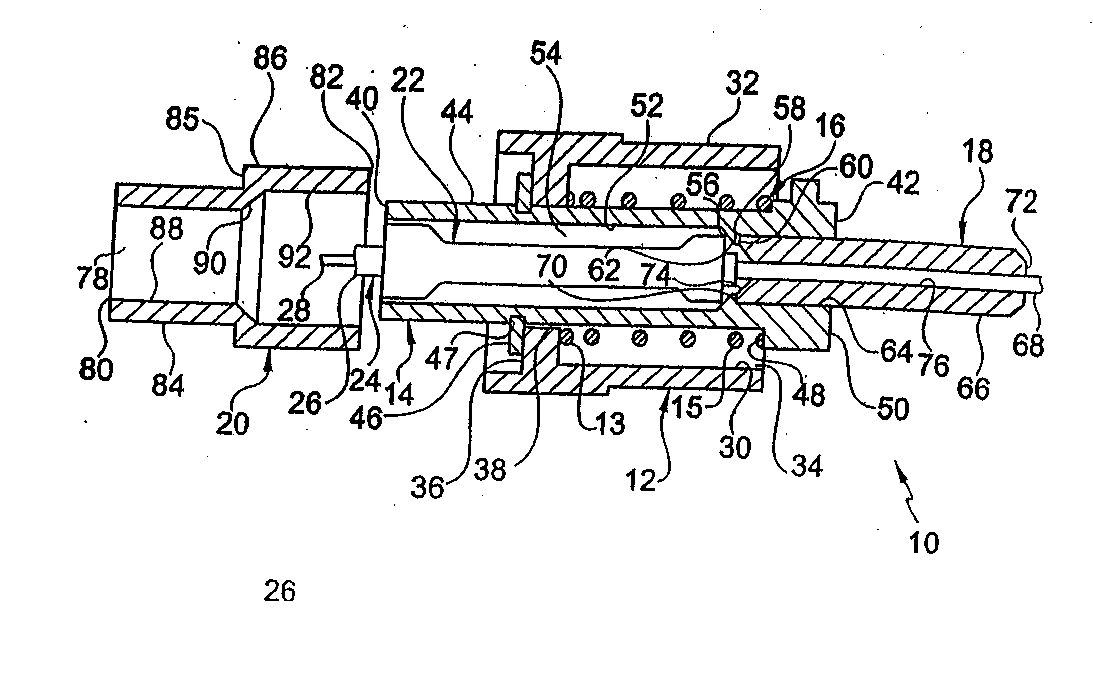
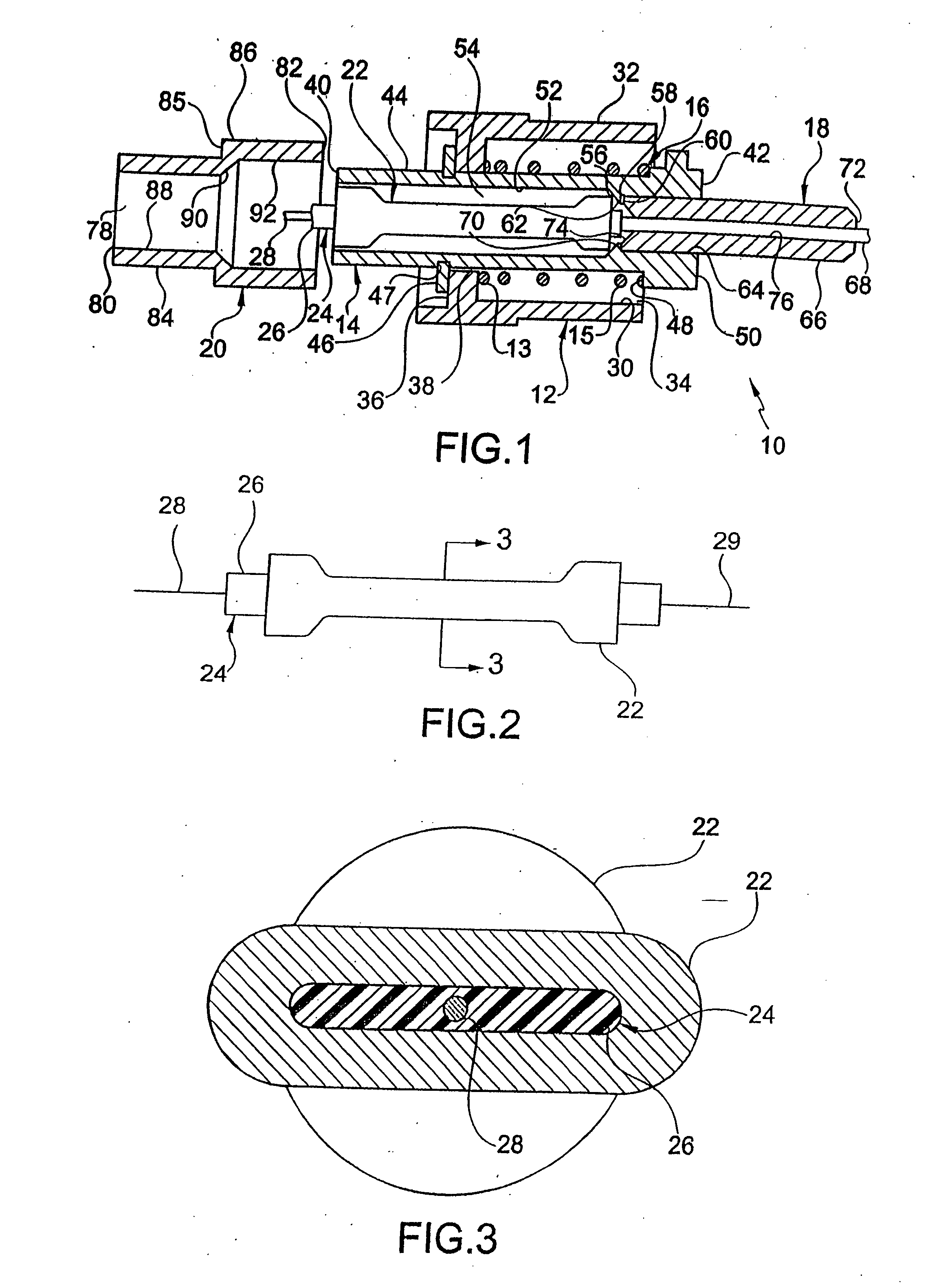
[0047] Referring initially to FIGS. 1-3, a strain relief connector 10 according to the present invention has a securing member or mechanism 12 surrounding a deformable connector body 14. Spring 16 is inserted between the securing member 12 and the connector body 14. The connector body 14 surrounds a portion of an alignment ferrule 18 and is coupled to a crimp ring 20. A deformable crimp tube or sleeve 22 is disposed within the connector body and the deformable crimp tube 22 is coupled to a fiber optic cable 24 having a cover 26 surrounding an optical fiber 28.

[0048] The securing member 12 is preferably a tubular or round metal threaded or bayonet type nut known in the pertinent art, such as an FC or ST type connector or any other suitable connector. The securing member does not necessarily have to be tubular, round, or metal and may be any type of securing device that can be connected to the deformable connector body 14 receiving deformable crimp tube 22.

[0049] Preferably, the secu...

embodiment

of FIG. 8

[0066] As seen in FIG. 8, metal connector body 214 has a plastic or metal alignment ferrule 218, inserted therein, as described above. Ferrule 218 is substantially similar to ferrule 18 and the description of ferrule 18 is applicable to ferrule 218. In the present embodiment, body 214 has an inner cylindrical surface 224 adjacent first open end 226 defining a through passageway 228 therethrough. Surface 224 is adjacent axially facing outwardly extending surface 230 that extends to cylindrical surface 232, which terminates at second open end 234. Surface 232 defining a through passageway 236 that is larger in diameter than through passageway 228.

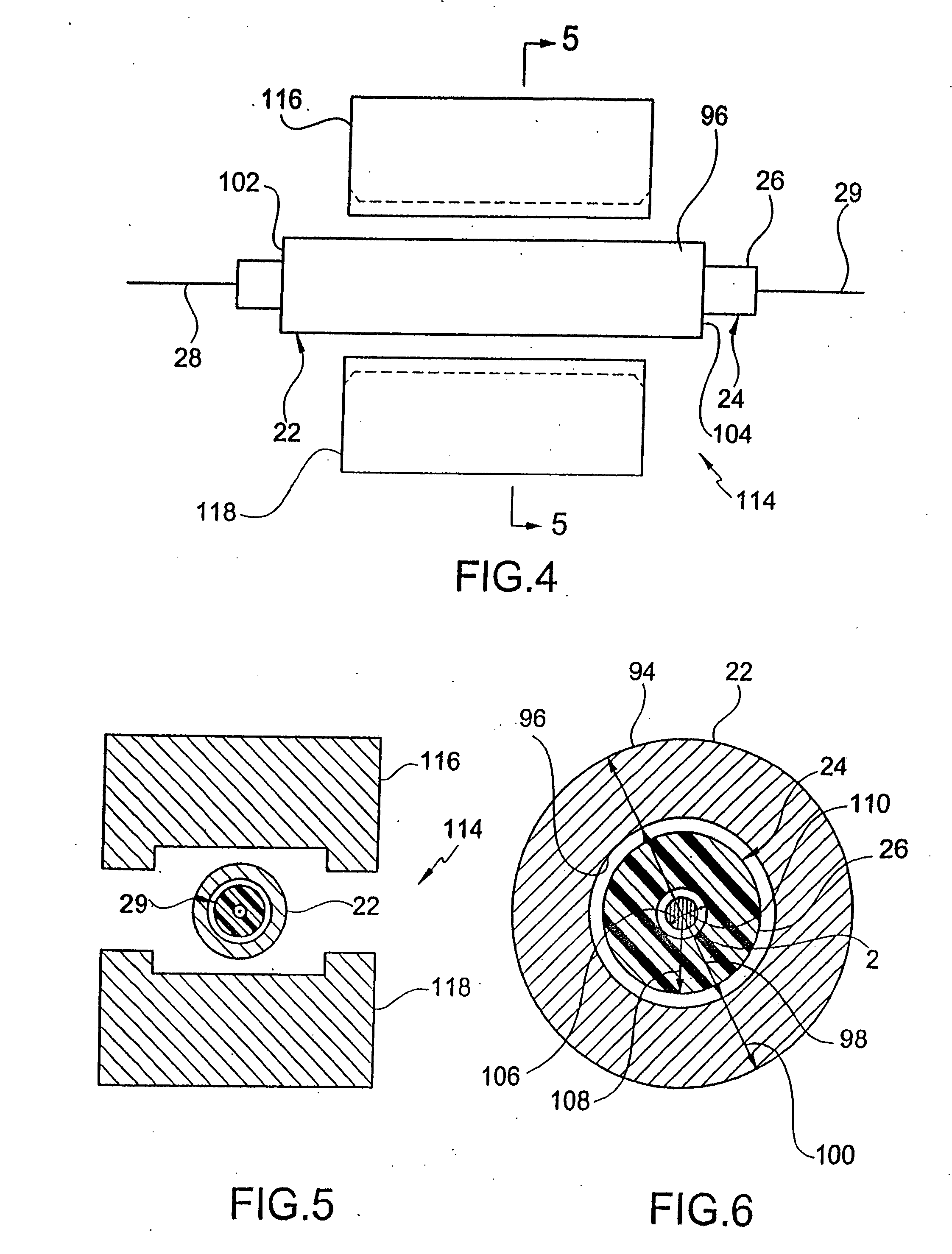
[0067] Ferrule 218 may be inserted though second end 234 and one end of ferrule 218 abutting surface 230. In this configuration, the crimp, using a long flat crimp die similar to die 114 shown in FIGS. 4 and 5, is performed directly onto the connector body 214. Disposed within the connector body prior to crimping may be an fiber opt...


PUM

PropertyMeasurementUnit
outer diameteraaaaaaaaaa
inner diameteraaaaaaaaaa
diameteraaaaaaaaaa

Abstract

Crimp tool is for and a method forms a strain relief connector including an optical fiber, a cover enclosing the optical fiber. The cover has an inner surface, an outer surface, a first end and a second end, the first end having a tapered portion that extends radially outwardly. A sleeve surrounds the cover and has a first inner volume and a first interior shoulder, a portion of the outer surface of the tapered portion abuts the first interior shoulder. The sleeve and the cover are simultaneously compressed forming a compressed portion. The cover and the sleeve are deformed such that the cover substantially fills the first inner volume of the sleeve.

Description

REFERENCE TO RELATED APPLICATION [0001] This patent application is a division of U.S. patent application Ser. No. 10 / 740,888 entitled Crimp Tool for Strain Relief Connector and Method of Forming a Strain Relief Connector and filed on Dec. 22, 2003, which is a division of U.S. patent application Ser. No. 10 / 115,429 entitled Strain Relief Connector for Fiber Optic Cable and Method of Making Same and filed Apr. 4, 2002, and is a continuation-in-part of U.S. patent application Ser. No. 09 / 565,489, entitled Strain Relief Connector for Fiber Optic Cable and Method of Making Same and filed May 5, 2000, now U.S. Pat. No. 6,390,688, the subject matter of each of which is hereby incorporated by reference. FIELD OF THE INVENTION [0002] The present invention relates to a crimping tool for and a method for forming a non-adhesive strain relief connector for a fiber optic cable. More particularly, the present invention relates to an optical fiber and cover that are disposed with in a metal sleeve,...

Claims


Application Information

Patent Timeline
Patent Type & Authority Applications(United States)
IPC IPC(8): G02B6/36G02B6/38
CPCG02B6/2558Y10T29/53226G02B6/3821G02B6/3838G02B6/3846G02B6/3857G02B6/3869G02B6/3887G02B6/3894G02B6/3898Y10T29/53222Y10T29/49181Y10T29/53213Y10T29/49183G02B6/3807G02B6/3809G02B6/382G02B6/3888
Inventor LUTZEN, JON A.MONTGELAS, RUDOLPH A.MILLER, ALAN C.
Owner LUTZEN JON A
Why Eureka
Try Eureka