Grain cleaning system for a combine harvester

a technology of combine harvester and cleaning system, which is applied in the direction of agriculture, agricultural tools and machines, solid separation, etc., can solve the problems of grain loss, crop drop, and ineffective use of available area of siev

Active Publication Date: 2005-12-22
BLUE LEAF I P
View PDF13 Cites 45 Cited by
  • Summary
  • Abstract
  • Description
  • Claims
  • Application Information

AI Technical Summary

Benefits of technology

[0018] The length of the actuator will determine the mean position of the pivot axis of the pivot arm and will therefore set the inclination of the path followed by the sieve. Furthermore, as the actuator is itself mounted on the rocker plate, it will automatically superimpose an os

Problems solved by technology

A problem is experienced with combine harvesters when operating on the side of a hill because the grain and MOG tend to accumulate on the downhill side of the sieve.
The consequent pressure drop also affects the crop-loaded areas, such that less MOG is lifted up and blown out of the combine harvester.
Moreover, the available area of the sieve is not used effectively; grain mingled with MOG remains concentrated near the lower side of the sieve and grain loss occurs because many kernels are conveyed out of the combine harvester, together with the MOG

Method used


Image

  • Grain cleaning system for a combine harvester
  • Grain cleaning system for a combine harvester
  • Grain cleaning system for a combine harvester

Examples


Embodiment Construction

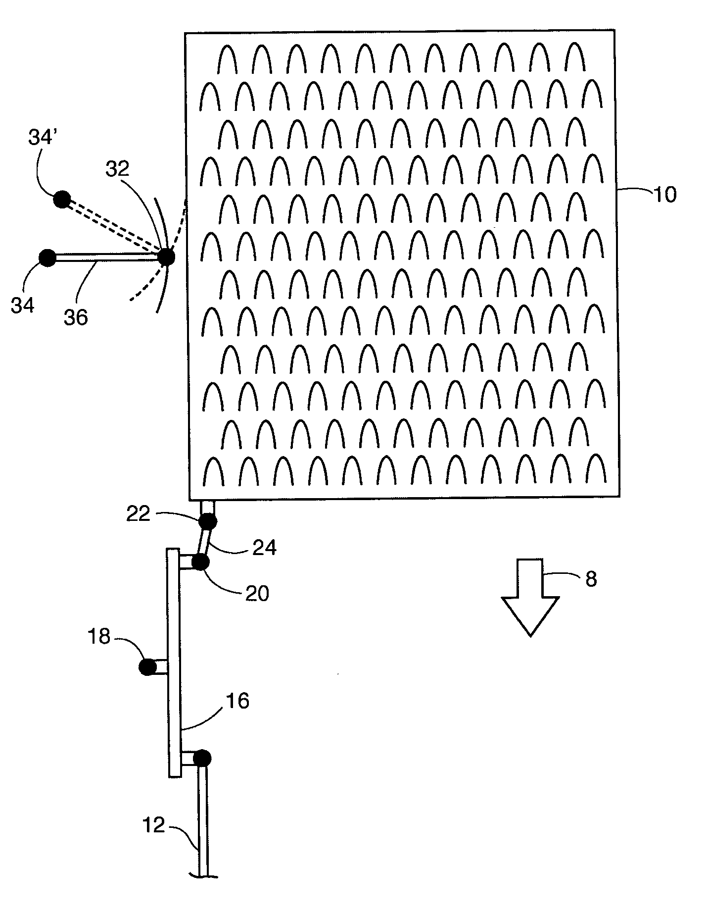
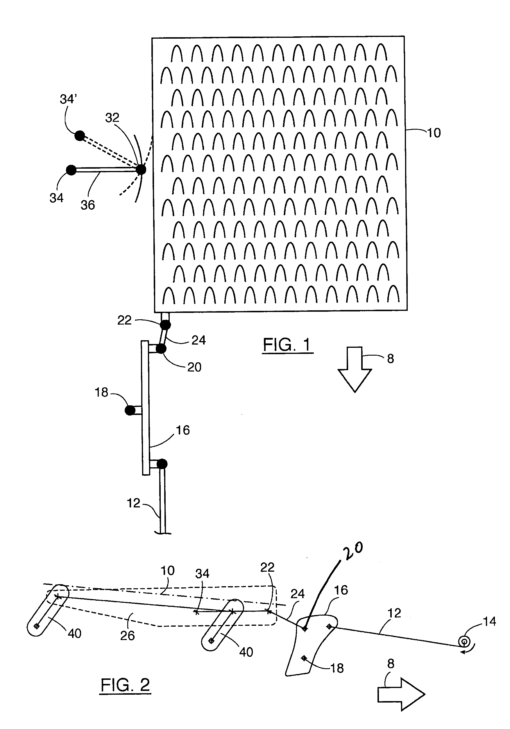
[0037] The apparatus of FIGS. 1 and 2 operates on the same principle as the apparatus described in GB 2146218. For this reason, the apparatus has only been shown schematically to permit an understanding of the invention but reference may be made to GB 2146218 for a more detailed description of its construction.

[0038] A sieve 10 is mounted in the combine harvester in such a matter that it can be moved freely both fore and aft and from side to side. As illustrated in FIG. 2, the sieve 10 in the illustrated apparatus is supported from below by posts 40 having rubber bushes at both ends to permit them to pivot in mutually orthogonal planes. It is however alternatively possible to suspend the sieve 10 from above, as illustrated in FIG. 1 of GB 2146218.

[0039] To move the sieve 10 in the fore and aft direction, that is to say parallel to the direction of movement 8 of the combine harvester, a cranking mechanism comprising a crank 14 or eccentric mechanism is connected to a connecting rod...


PUM


Abstract

A drive linkage is described for reciprocating a sieve that is suspended within a frame of a combine harvester for movement in mutually orthogonal directions. The drive linkage comprises a cranking mechanism for imparting a reciprocating motion to the sieve in the direction of travel of the harvester and a pivot arm pivotably connected at one end to one side of the sieve to cause the sieve to move in an arc centred on a pivot axis at the opposite end of the pivot arm as the sieve is reciprocated. In the invention, the pivot axis of the pivot arm is displaced relative to the frame in synchronism with the reciprocation of the sieve in such a manner as to cause the sieve to follow a substantially rectilinear path relative to the frame.

Description

CROSS REFERENCE TO RELATED PATENT APPLICATIONS [0001] This Patent Application claims priority under 35 U.S.C. § 119 to GB 0413957.2, filed on Jun. 22, 2004 titled, “Grain Cleaning System for a Combine Harvester”, the full disclosure of which is hereby fully incorporated herein by reference. FIELD OF THE INVENTION [0002] The present invention relates to a combine harvester and is particularly concerned with a drive linkage employed to reciprocate the sieves of a combine harvester to separate the grain from the remainder of the crop material. BACKGROUND OF THE INVENTION [0003] In a combine harvester, after a crop has been cut, it is passed through a thresher, which acts to separate the grain from the stalks or the straw. The straw is transported to the back of the harvester while the grain and other crop particles drop onto a sieve. The material other than grain (MOG) comprises chaff, short straw and other particles that the thresher has separated from the longer straw stems. [0004] T...

Claims


Application Information

Patent Timeline
IPC IPC(8): A01D75/28
CPCA01F12/448A01D75/282
Inventor DUQUESNE, FRANK R.G.SOMERS, TOM N.N.
Owner BLUE LEAF I P
Why Eureka
Try Eureka