
Method and apparatus for producing composite cigarette filters

a technology of composite cigarette filters and filter rods, which is applied in the direction of tobacco smoke filters, packaging, packaged goods, etc., can solve the problems of affecting cigarette performance and undesirable, and the generation of waste combined filter rods, of course, undesirabl

Active Publication Date: 2005-12-22
PHILIP MORRIS USA INC
View PDF9 Cites 42 Cited by
  • Summary
  • Abstract
  • Description
  • Claims
  • Application Information

AI Technical Summary

Benefits of technology

The present invention provides apparatus and methods for producing composite cigarette filters with improved precision and efficiency. The apparatus includes a means for forming a continuous sequence of segments and transporting it along a path to a wrapping means, where it is cut into discrete rods. The method also includes maintaining the positioning of the segments to prevent relative movement during transportation. The technical effects of this invention include improved precision in the production of external filter rod segment length and air gap length, increased machine speed, reduced waste, and lower maintenance requirements.

Problems solved by technology

Known apparatus for the production of composite filters suffers from the disadvantage that the plurality of filter rod segments making up the composite filter, having been assembled into the desired combined filter or recess filter configuration by the combining device, are free to move relative to one another before being wrapped in the web of paper and thereby fixed in position.
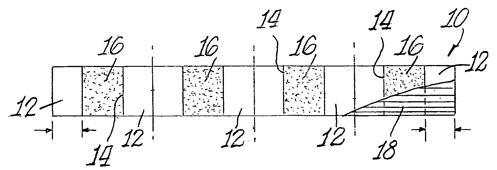
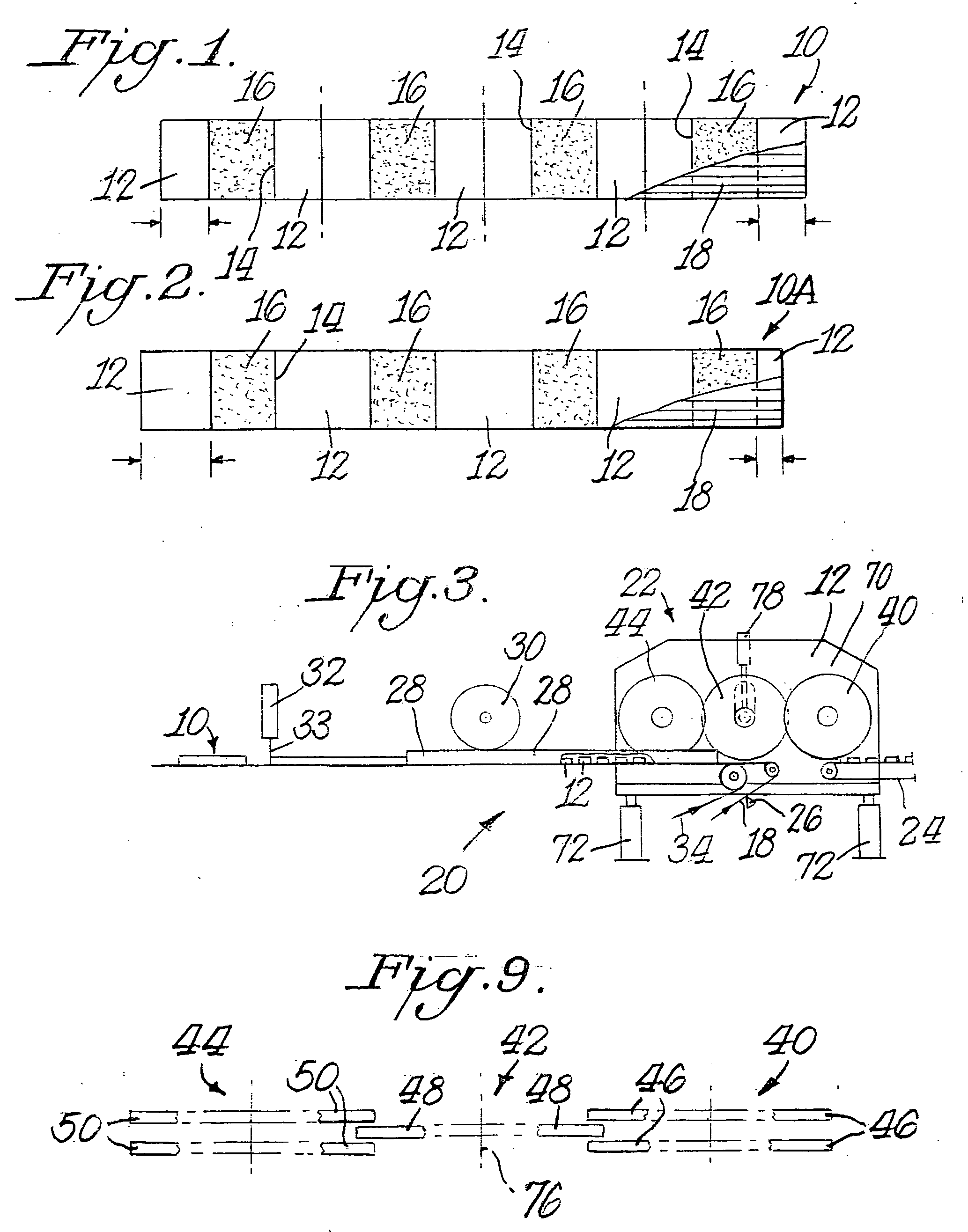
As a result, the filter rod segments making up the composite filter are not always in the correct position within the continuous filter rod at the point at which it is severed, resulting in the formation of discrete composite filter rods having external filter rod segments of differing length, as illustrated in FIG. 2.
Variations in cavity volume in filled plug-space-plug filter configurations can affect cigarette performance and is undesirable.
The generation of waste combined filter rods is, of course, undesirable.

Method used


Image

  • Method and apparatus for producing composite cigarette filters
  • Method and apparatus for producing composite cigarette filters
  • Method and apparatus for producing composite cigarette filters

Examples


Embodiment Construction

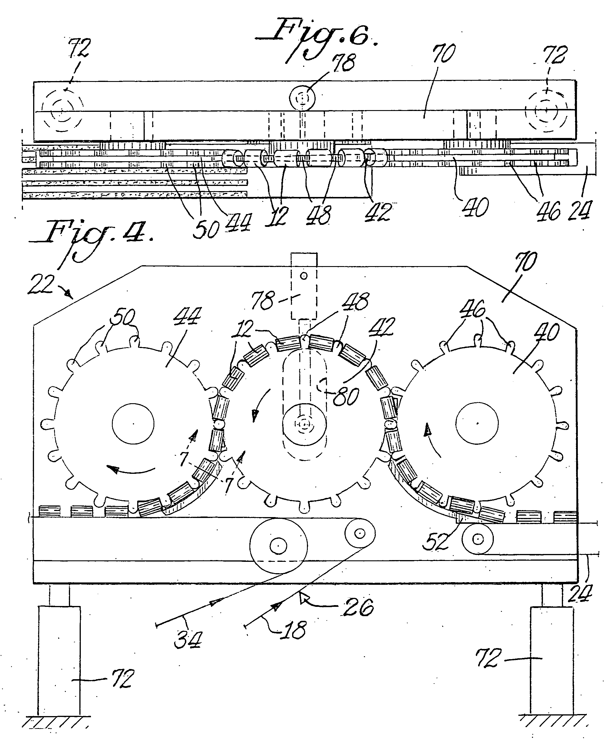
[0027] Referring in more particularity to the drawings, FIG. 3 schematically illustrates apparatus 20 for continuously producing the filter rods 10 shown in FIG. 1. Fundamentally, filter segments 12 are delivered to a spacer wheel assembly 22 by a first endless belt conveyor 24. As explained more fully below, the spacer wheel assembly 22 receives filter segments 12 from the belt conveyor 24 and ultimately deposits the segments on the surface of endless plug wrap 18 to which adhesive has been applied by a glue applicator 26. The plug wrap 18 is drawn from a bobbin (not shown), and the filter segments 12 are placed onto the plug wrap 18 in precisely spaced apart relationship, as explained more fully below.

[0028] The plug wrap 22 is partially folded around the spaced apart filter segments 12 by a garniture 28 and granular material 16 is then deposited in the cavities 14 between the filter segments by a filling wheel 30. It is to be realized that the garniture 28 includes a portion und...


PUM


Abstract

Method and apparatus for producing discrete filter rods includes a first conveyor for transporting filter segments of given length in a downstream direction. Three counter rotating transfer wheels receive the filter segments between spaced apart cleats on the circumference of the wheels. The first wheel receives the filter segments from the first conveyor and transfers the segments to the second wheel which in turn transfers the segments to the third wheel. Filter segments between the cleats on the third wheel are deposited upon a second conveyor with plug wrap thereon in precisely spaced apart relationship. Granular adsorbent material is filled into cavities between the filter segments, and a garniture folds the plug wrap around the filter segments and the filled cavities therebetween.

Description

BACKGROUND OF THE INVENTION [0001] The present invention relates to method and apparatus for producing rods comprising multiple segments and finds particular application in the manufacture of combined filters or recess filters for cigarettes. [0002] Cigarettes typically comprise a wrapped tobacco column that optionally is tipped with a filter. The filter, in turn, may optionally be a composite filter comprising a plurality of (possibly dissimilar) filter rod segments. The dissimilar filter rod segments making up the composite filter may, for example, include different base filter materials or may comprise the same base filter material, but with alternate segments being impregnated with a particulate material such as carbon particles. Alternatively, the filter may comprise spaced apart filter material segments with fillable cavities therebetween for receiving adsorbent particles such as carbon granules, for example. Still another alternative is that the cavities not be filled and the...

Claims


Application Information

Patent Timeline
Patent Type & Authority Applications(United States)
IPC IPC(8): A24D3/02B31C99/00
CPCA24D3/0287A24D3/0225
Inventor GARTHAFFNER, MARTIN T.ERCELEBI, AHMETEVANS, JAMES D.STRAIGHT, JEREMY
Owner PHILIP MORRIS USA INC
Learn More