Switch device

Active Publication Date: 2005-12-29
NILES PARTS CO LTD +1
View PDF4 Cites 0 Cited by
  • Summary
  • Abstract
  • Description
  • Claims
  • Application Information

AI Technical Summary

Benefits of technology

[0019] Also, at the time of the tilting operation by pushing the push operation body, a rubbing feeling can be suppressed, and the feeling of operation of the push operation body can be improved.
[0020] In the case where the push operation body includes a flange disposed in the switch case, and a push portion protruding outward from the opening to the switch case and the supporting portion and the supported portion are separately provided to the flange and an inner surface of the switch case opposite to the flange, rotational support and positional regulation of the flange with respect to the switch case can be performed by the supporting portion and the supported portion. With this, a rubbing noise can be suppressed and the feeling of operation can be improved.
[0021] In the case where the flange has a square shape in a plane view and the supporting portion and the supported portion are separately provided to a corner portion of the flange and a portion of an inner surface of the switch case opposite to the corner portion of the flange, the push operation body can have four positions between the corner portions as push positions, thereby improving a function of a switch device.
[0022] In the case where a swelled portion in a plane direction is provided at the corner portion of the flange and the supporting portion and the supported portion are separately provided to the swelled portion and a portion of the inner surface of the switch case opposite to the swelled portion, a distance between a point for rotational support and positional regulation by the supporting por

Problems solved by technology

However, the above-described structure poses problems such that, at the time of a tilting operation of the pu

Method used


Image

  • Switch device
  • Switch device
  • Switch device

Examples


Example

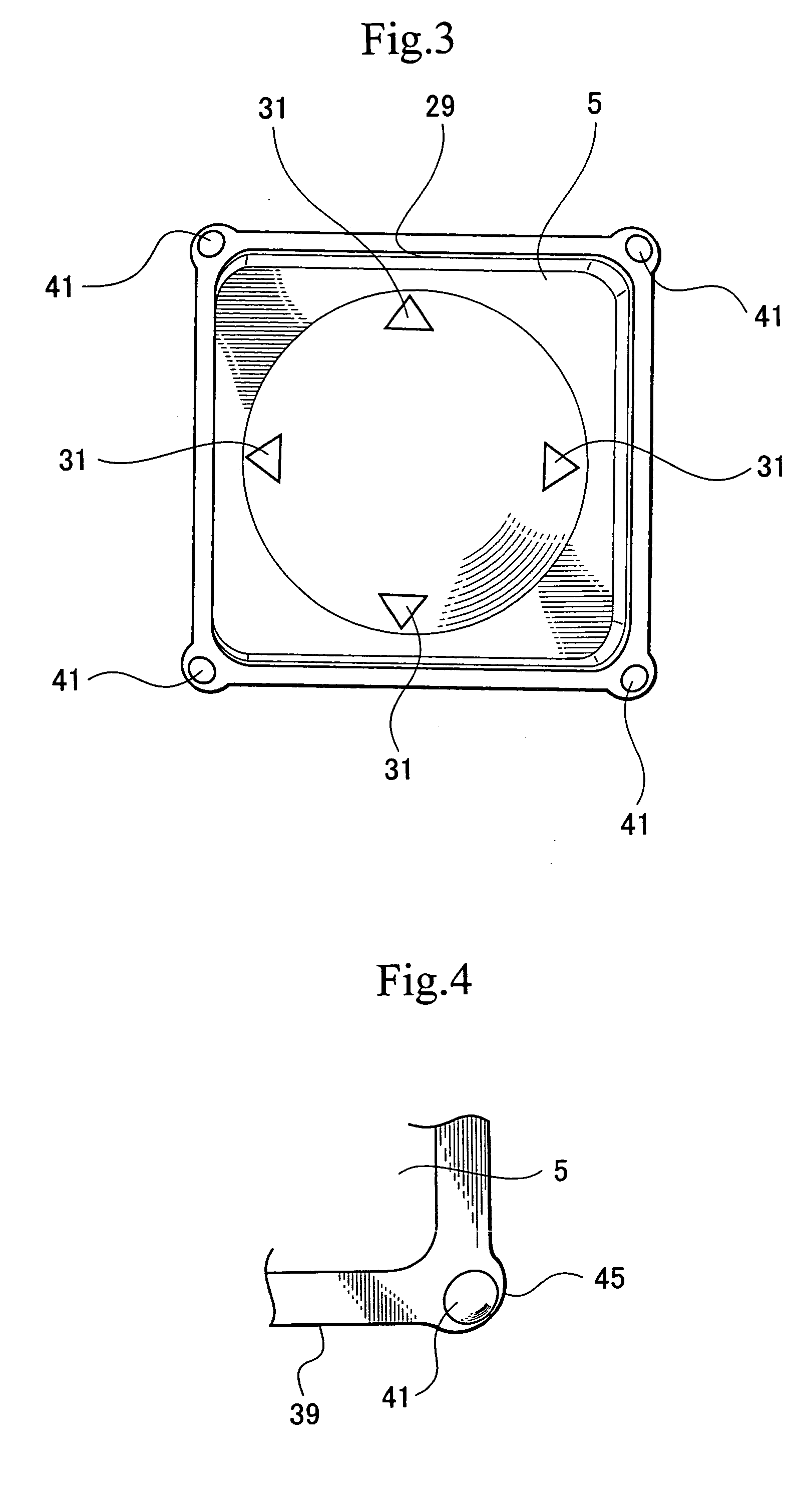
[0037] Objects of the present invention, that is, suppression of a rubbing sound and an improvement in the feeling of operation, are achieved by providing a supporting portion and a supported portion.

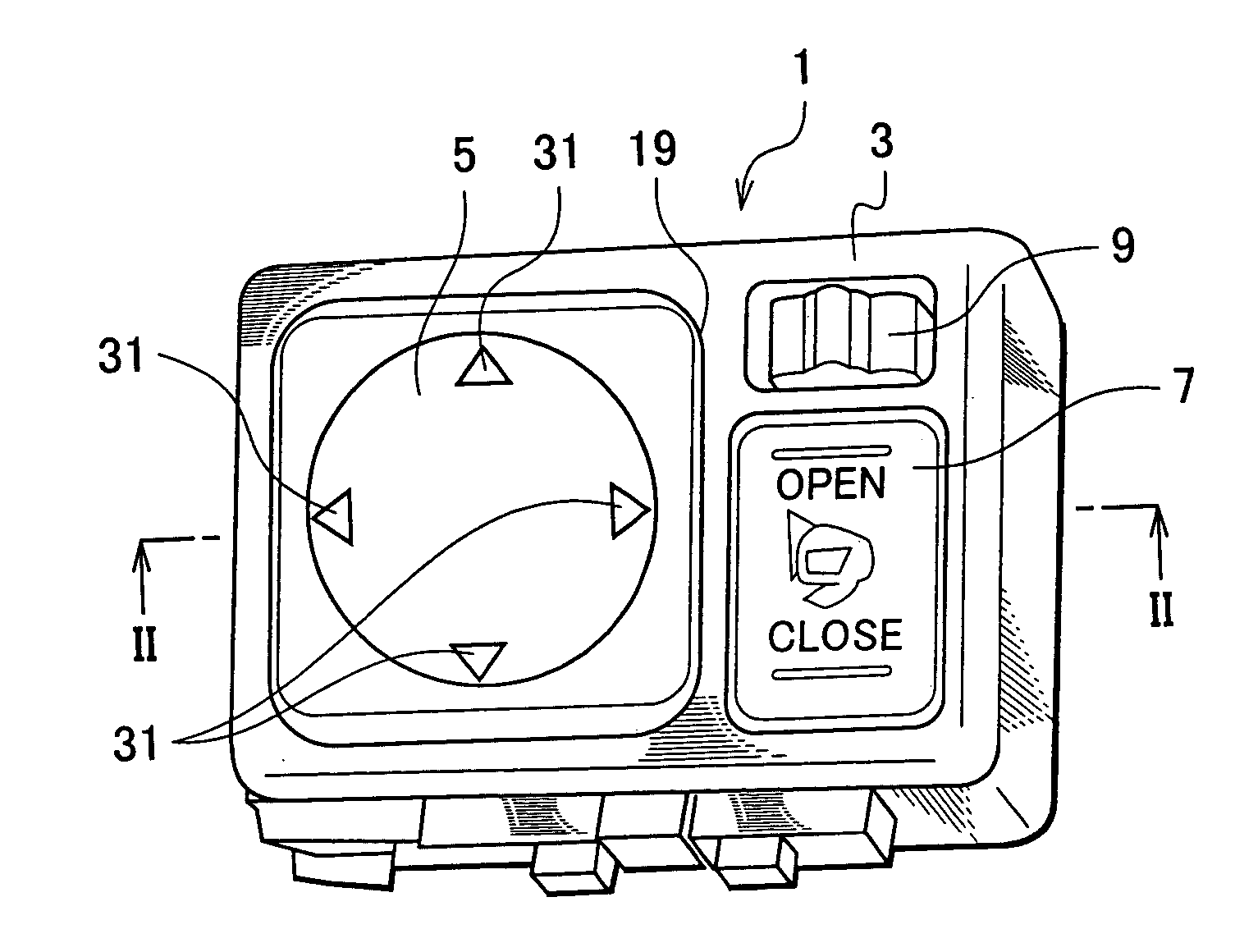
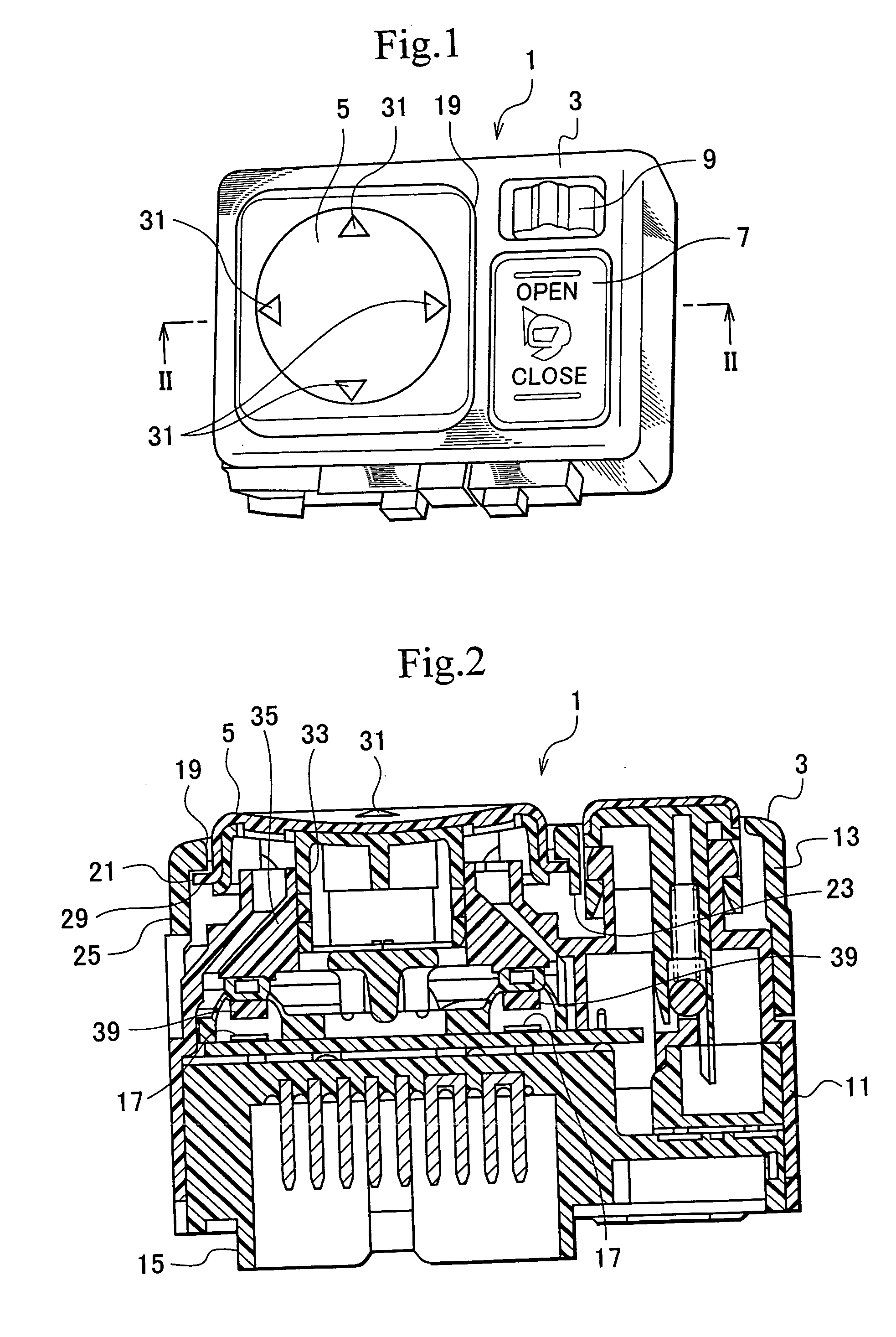
[0038]FIGS. 1 and 2 show a switch device to according to an embodiment of the present invention. FIG. 1 is a perspective view of the switch device, and FIG. 2 is a sectional view thereof taken along a line II-II of FIG. 1. A switch device 1 illustrated in FIGS. 1 and 2 are, for example, to operate a right or left door mirror of a vehicle. The switch device 1 includes a push button 5 serving as a push operation body, a seesaw switch 7, and a slide switch 9 on a switch case 3.

[0039] The push button 5 is to change and adjust the direction of a mirror surface of a right or left door mirror upward, downward, rightward, or leftward. The seesaw switch 7 has an open-operation portion and a close-operation portion. Upon an operation on one of these portions, the position of the door mirror can...


PUM


Abstract

In a switch device including: a push button disposed in an opening of a switch case and operable to be tilted in any one of a plurality of directions by being pushed at an outer edge side; a rubber contact that forces the push button to a position before pushing; and a movable contact and a fixed contact connectable to each other by each pushing operation on the push button, a convex portion and a concave portion that can be spaced apart from each other are separately provided to the push button and the switch case for rotational support and positional regulation of the push button with respect to the switch case at the time of a tilting operation by each pushing.

Description

BACKGROUND OF THE INVENTION [0001] 1. Field of the Invention [0002] The present invention relates to a switch device for use as, for example, a door mirror switch of a vehicle. [0003] 2. Description of the Related Art [0004] An example of a conventional switch device of this type is disclosed in Japanese Patent Laid-Open Publication No. 11-288644, and is shown in FIGS. 10 and 11. FIG. 10 is a plan view of a conventional switch device, and FIG. 11 is a sectional view thereof. [0005] A switch device 101 shown in FIGS. 10 and 11 is used for, by way of example, changing and adjusting the direction of a mirror surface of a left or right door mirror upward, downward, rightward, or leftward. The switch device 101 includes a push button 107 as a push operation body provided to an opening 105 of a switch case 103. [0006] The push button 107 is provided with four convex portions 109 as markers corresponding to up, down, right, and left movements of the door mirror to indicate push operation p...

Claims


Application Information

Patent Timeline
IPC IPC(8): H01H25/04
CPCH01H25/041H01H2300/012H01H2221/058H01H2025/046H01H25/04
Inventor SEKINO, YUTAKAONODERA, HIDEJIFUJIMOTO, TAKESHI
Owner NILES PARTS CO LTD
Why Eureka
Try Eureka