AC pulse arc welding method

a pulse arc welding and alternating current technology, applied in the field of alternating current pulse arc welding methods, can solve the problems of inability to form proper weld beads with a low wire feeding speed and a small amount of deposition, shortage of deposition, and negative current rate ren will inevitably change, so as to achieve the effect of convenient operation

Active Publication Date: 2005-12-29
DAIHEN CORP
View PDF3 Cites 16 Cited by
  • Summary
  • Abstract
  • Description
  • Claims
  • Application Information

AI Technical Summary

Benefits of technology

[0032] According to the present invention, the welding current setting value Is determines the welding current average Iav, and the electrode negative current rate setting value Rs determines the electrode negative current rate Ren, and the wire feeding speed setting value Fsc is automatically calculated by a conversion function. In this manner, the setting of the welding current average Iav can be conducted independently of the setting of the negative current rate Ren. As a result, the setting of the heat input to the base material (this settin

Problems solved by technology

Unfavorably, it is difficult to form proper weld beads with a low wire feeding speed and a small amount of deposition.
In particular, when there is a gap between the metallic parts to be welded, the shortage of deposition is crucial.
In the conventional manner, how

Method used


Image

  • AC pulse arc welding method
  • AC pulse arc welding method
  • AC pulse arc welding method

Examples


Embodiment Construction

[0045] Preferred embodiments of the present invention will be described below with reference to the accompanying drawings.

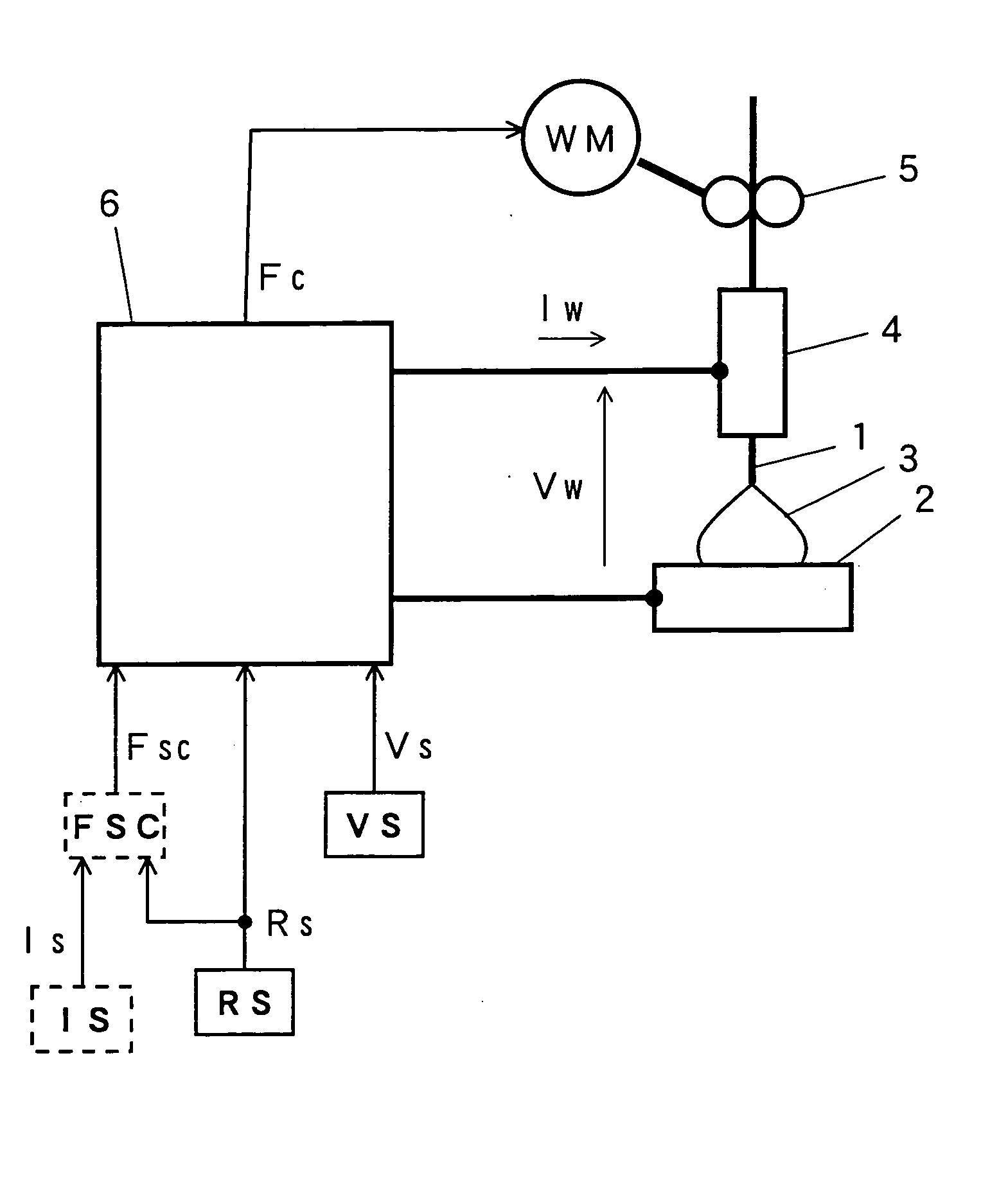
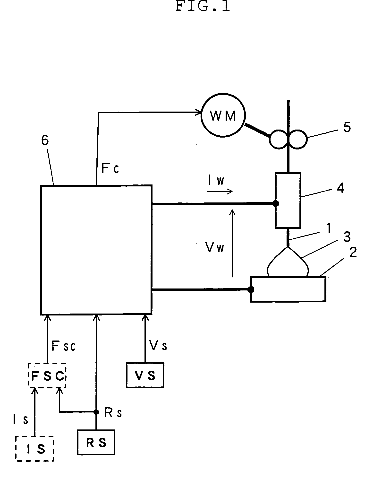
[0046]FIG. 1 shows an AC pulse arc welder used for implementing a welding method according to the present invention. In the figure, the elements identical or similar in function to those shown in FIG. 7 are designated by the same reference numerals or characters used in FIG. 7. Specifically, the elements represented in solid lines may be the same for both the conventional welder (FIG. 7) and the welder of the present invention (FIG. 1), while the elements represented in broken lines in FIG. 1 have no counterparts in the conventional system shown in FIG. 7.

[0047] As shown in FIG. 1, the welding current setting circuit IS outputs a welding current setting signal Is for setting a welding current average. The wire feeding speed conversion circuit FSC receives the above-mentioned welding current setting signal Is and an electrode negative current rate setting signal...


PUM

PropertyMeasurementUnit
Speedaaaaaaaaaa
Currentaaaaaaaaaa

Abstract

In accordance with an AC pulse arc welding method, a periodic welding current is applied, that includes, for a pulse cycle, negative current in electrode negative polarity and positive current in electrode positive polarity. Then, a negative current rate is set by a negative current rate setting value, where the negative current rate represents the ratio of the negative current to the welding current for the pulse cycle. Then, a feeding speed of welding wire as a consumable electrode is set by a feeding speed setting value. The method further includes: setting an average of the welding current by a welding current setting value; and performing automatic calculation of the feeding speed setting value by using a predetermined conversion function based on input of the welding current setting value and the negative current rate setting value.

Description

BACKGROUND OF THE INVENTION [0001] 1. Field of the Invention [0002] The present invention relates to an alternating current (AC) pulse arc welding method whereby the setting of welding conditions such as a wire feeding speed can be performed quickly and accurately. [0003] 2. Description of the Related Art [0004]FIG. 7 illustrates a conventional AC pulse arc welder, which includes a wire feeding speed setting circuit FS, a negative current rate setting circuit RS, and a welding voltage setting circuit VS. The wire feeding speed setting circuit FS outputs a signal (wire feeding speed setting signal Fs) for setting the feeding speed of a welding wire 1. The negative current rate setting circuit RS outputs a signal (negative current rate setting signal Rs) for setting a negative current rate Ren to be described below with reference to FIG. 8. The welding voltage setting circuit VS outputs a signal (welding voltage setting signal Vs) for setting the average Vav of welding voltage Vw appl...

Claims


Application Information

Patent Timeline
IPC IPC(8): B23K9/09B23K9/095B23K9/10B23K9/12
CPCB23K9/092B23K9/125B23K9/1062B23K9/0953
Inventor TONG, HONGJUNTODO, MICHITAKA
Owner DAIHEN CORP
Why Eureka
Try Eureka