Bill separator using frictional force

a frictional force and separator technology, applied in the field of bill separators, can solve the problems of difficult installation and repair of conventional bill separators, large amount of time consumed, etc., and achieve the effect of convenient installation and repair

Inactive Publication Date: 2005-12-29
NAUTILUS HYOSUNG
View PDF7 Cites 6 Cited by
  • Summary
  • Abstract
  • Description
  • Claims
  • Application Information

AI Technical Summary

Benefits of technology

[0007] The present invention is conceived to solve the aforementioned problems. An object of the present invention is to provide a bill separator in which bills can be correctly discharged on

Problems solved by technology

Thus, for such precise adjustment of the amount of overlap, an assembling expert and a specially designed jig are required along with the consu

Method used


Image

  • Bill separator using frictional force
  • Bill separator using frictional force
  • Bill separator using frictional force

Examples


Embodiment Construction

[0018] Hereinafter, a bill separator using frictional force according to a preferred embodiment of the present invention will be described in detail with reference to the accompanying drawings.

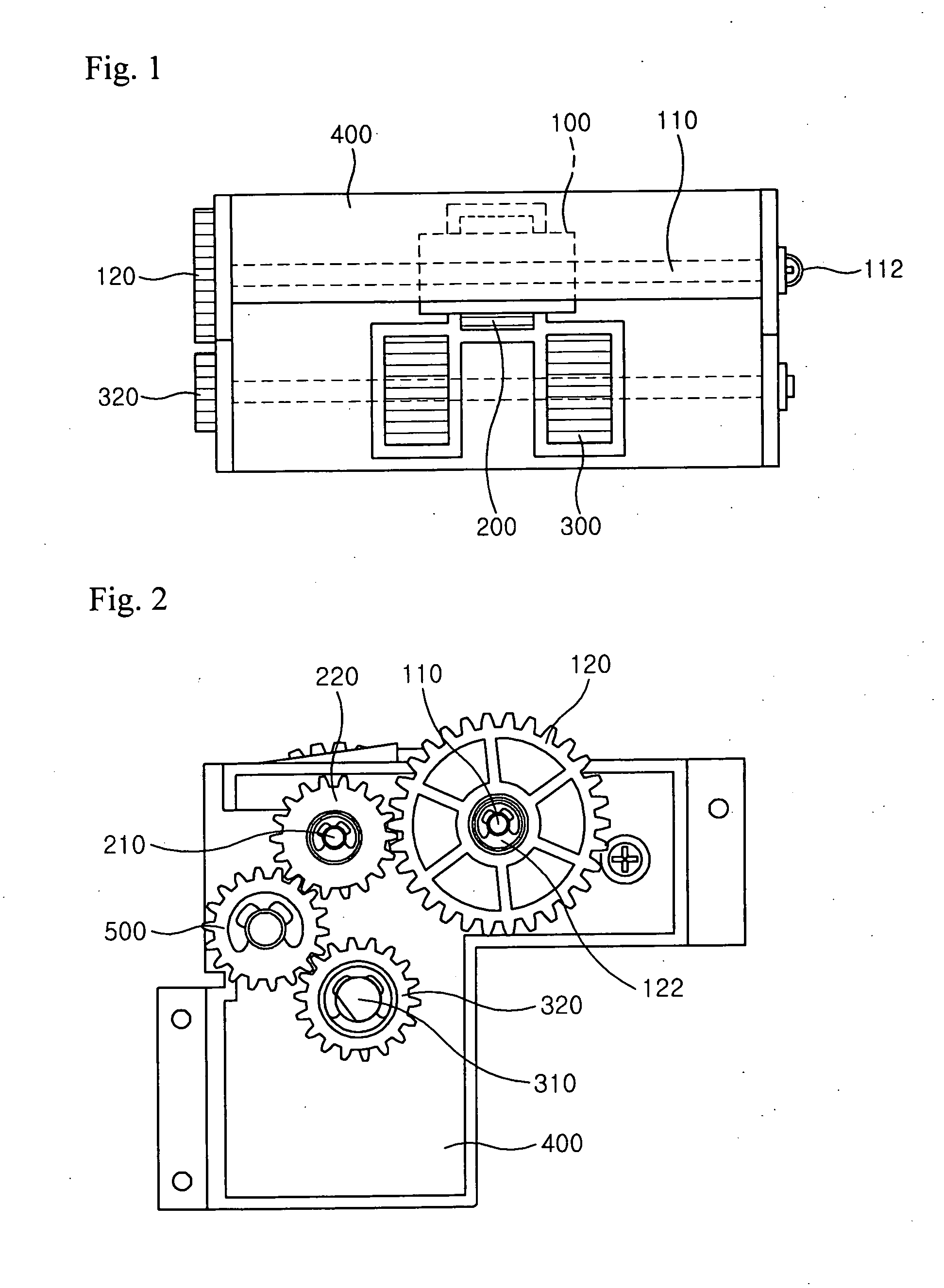
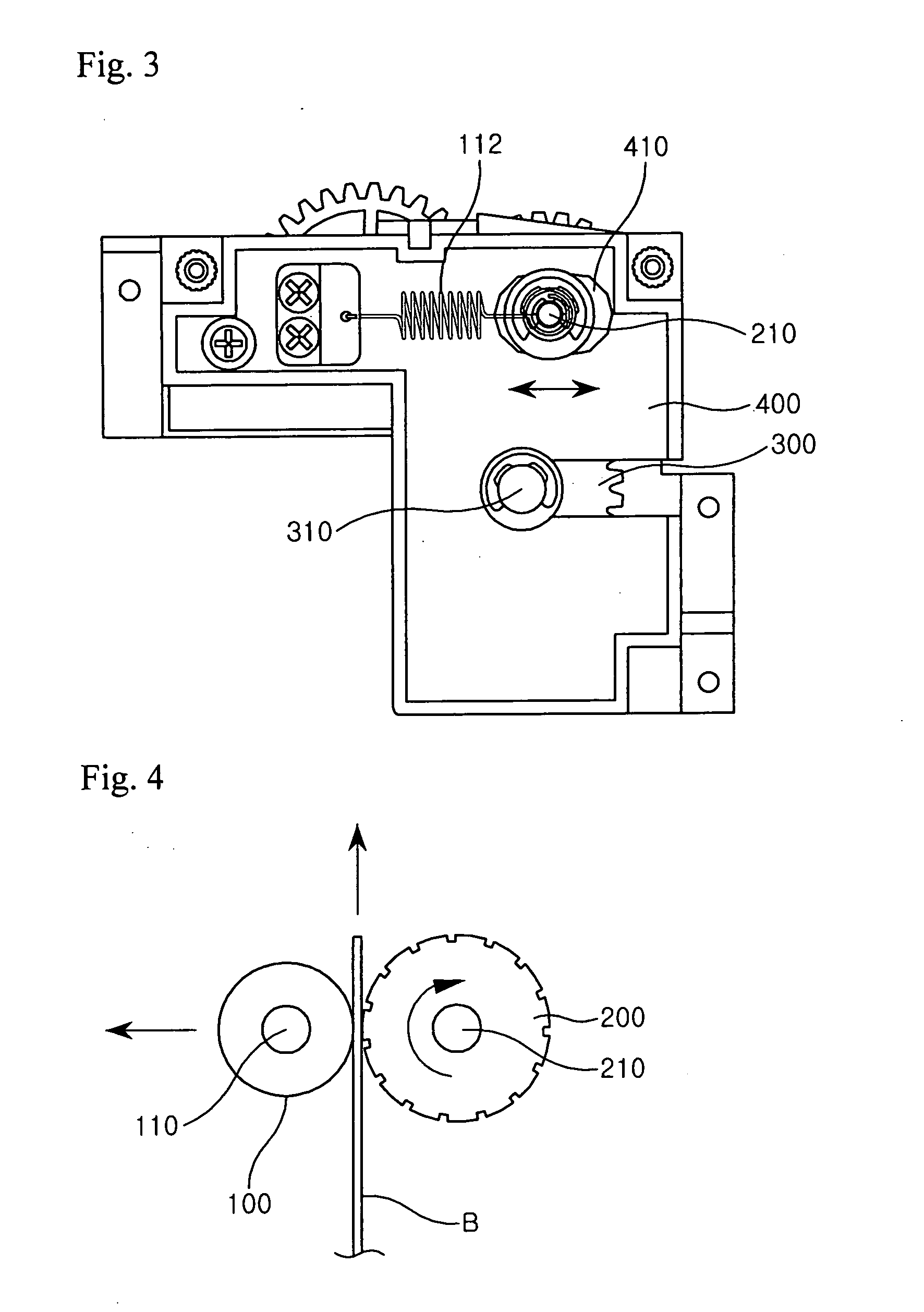
[0019] FIGS. 1 to 3 are a front view, a left side view and a right side view of a bill separator using frictional force according to an embodiment of the present invention, respectively.

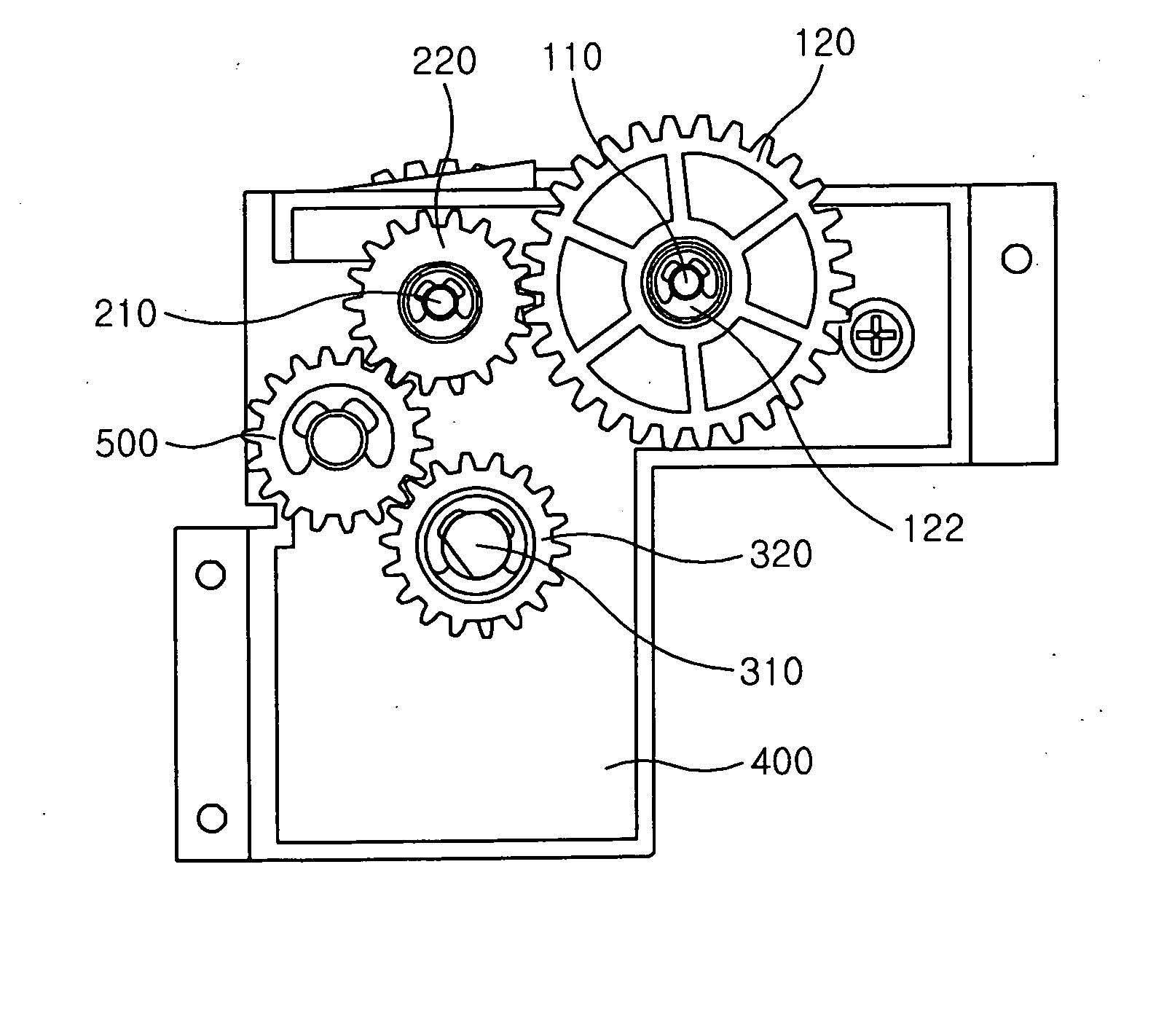
[0020] As shown in FIGS. 1 to 3, the bill separator using frictional force according to the present invention comprises a gate roller 100, a feeding roller 200, a pick-up roller 300, and a main body 400. The gate roller 100 is formed of a material with a friction coefficient higher than that of a bill and has a horizontal gate roller rotational shaft 110 coupled thereto along a central axis thereof. The gate roller 100 is constructed such that it cannot rotate in a bill-discharging direction but can rotate in a direction opposite to the bill-discharging direction. The feeding roller 200 is formed of a materia...


PUM


Abstract

The present invention provides a bill separator using frictional force, including a gate roller and a feeding roller which rotate in close contact with front and rear surfaces of a bill, respectively, to separate and discharge bills one by one, wherein the gate roller is formed of a material with a friction coefficient higher than that of the bill and constructed not to rotate in a bill-discharging direction, the feeding roller is formed of a material with a friction coefficient higher than that of the gate roller and constructed to rotate in the bill-discharging direction and to come into close contact with or be spaced apart from the gate roller, and an elastic means is further provided for causing the feeding roller to be in close contact with the gate roller with a certain magnitude of elastic force. With the bill separator using frictional force according to the invention, bills can be correctly discharged one by one so that the number of bills discharged can be coincident with the number of bills requested, and the bill separator can be easily installed and repaired without a skilled person and a special jig since possible abnormal changes in a gap between the gate roller and the feeding roller can be overcome simply by replacing the elastic means.

Description

BACKGROUND OF THE INVENTION [0001] 1. Field of the Invention [0002] The present invention relates to a bill separator for separating and discharging bills one by one, and more specifically, to a bill separator, wherein rotational shafts of feeding and gate rollers, which are in close contact with front and rear surfaces of an introduced bill, are coupled to each other by means of. a spring so that frictional force between the feeding and gate rollers and the front and rear surfaces of the bill can be kept constant. [0003] 2. Description of the Related Art [0004] A bill separator employed in an automated-teller machine should be operated in a very precise manner without an error, considering that it handles cash money. That is, when bills are discharged, the number of bills actually discharged should be coincident with the number of bills requested, by discharging them one by one without a phenomenon in which two or more bills are discharged at a time or any bills are not discharged....

Claims


Application Information

Patent Timeline
IPC IPC(8): B65H3/52B65H83/00B65H85/00G07F19/00
CPCB65H3/5246B65H2403/72G07F19/203B65H2701/1912G07F19/20B65H2404/531B65H3/06G07D2211/00G07F19/201G07D11/165
Inventor AHN, JIN HYUKLEE, WON JOONLEE, DONG SIK
Owner NAUTILUS HYOSUNG
Why Eureka
Try Eureka