

Piezoelectric power supply
- Summary
- Abstract
- Description
- Claims
- Application Information
AI Technical Summary
Benefits of technology
Problems solved by technology
Method used
Image

Examples
Embodiment Construction
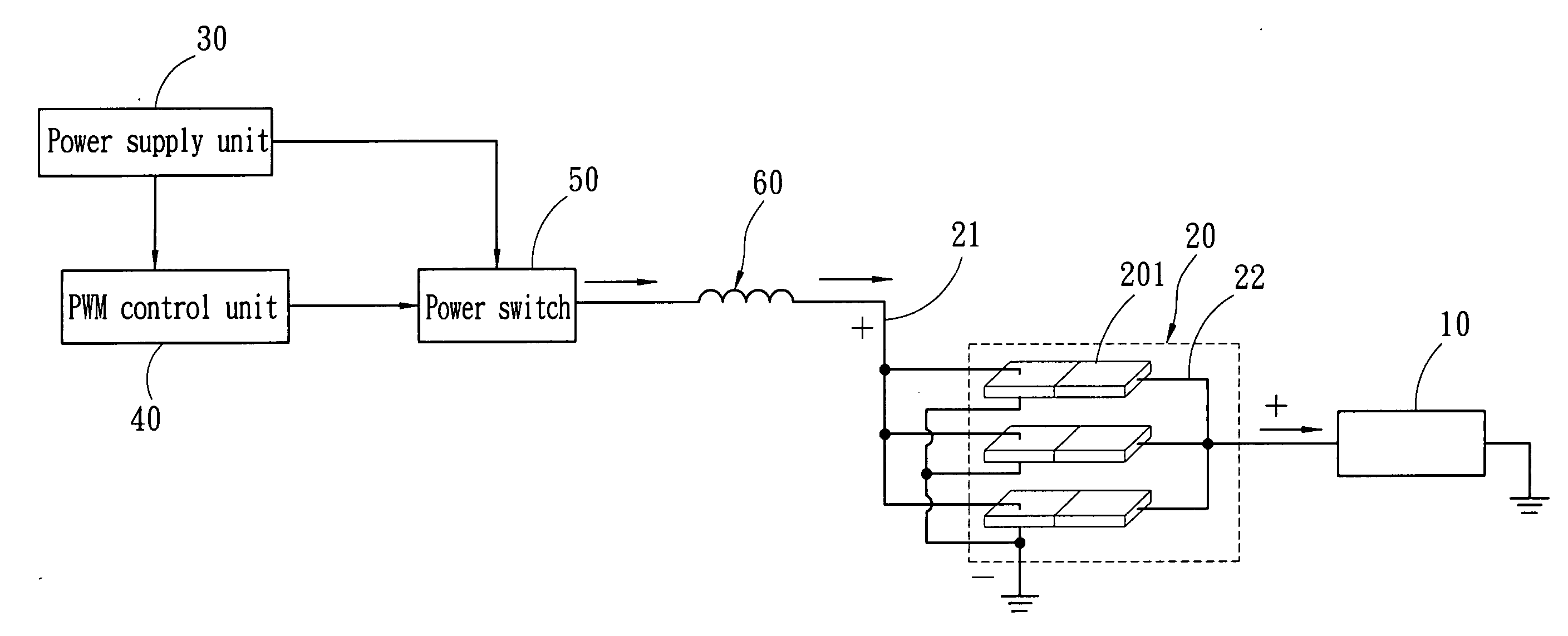
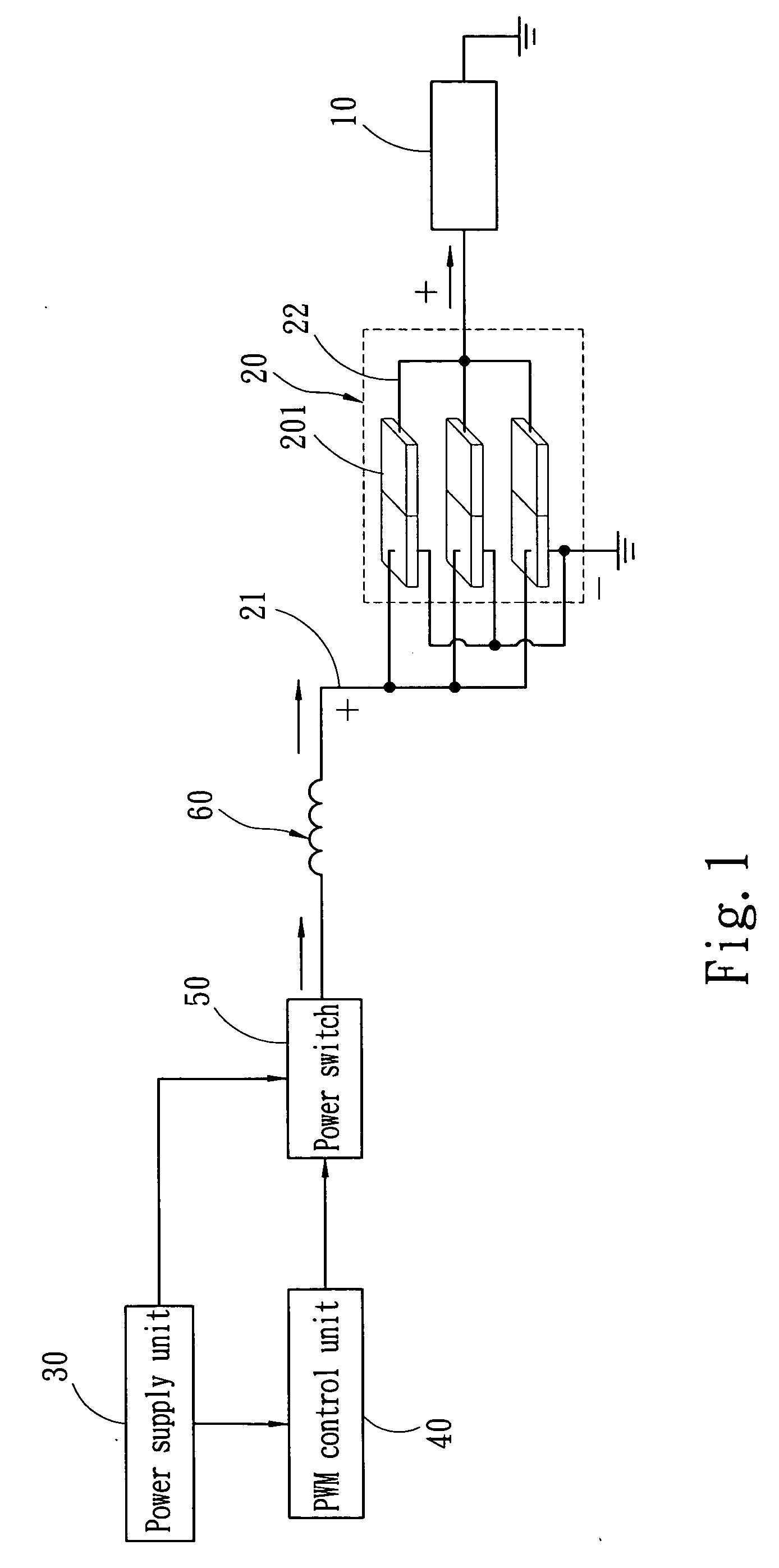
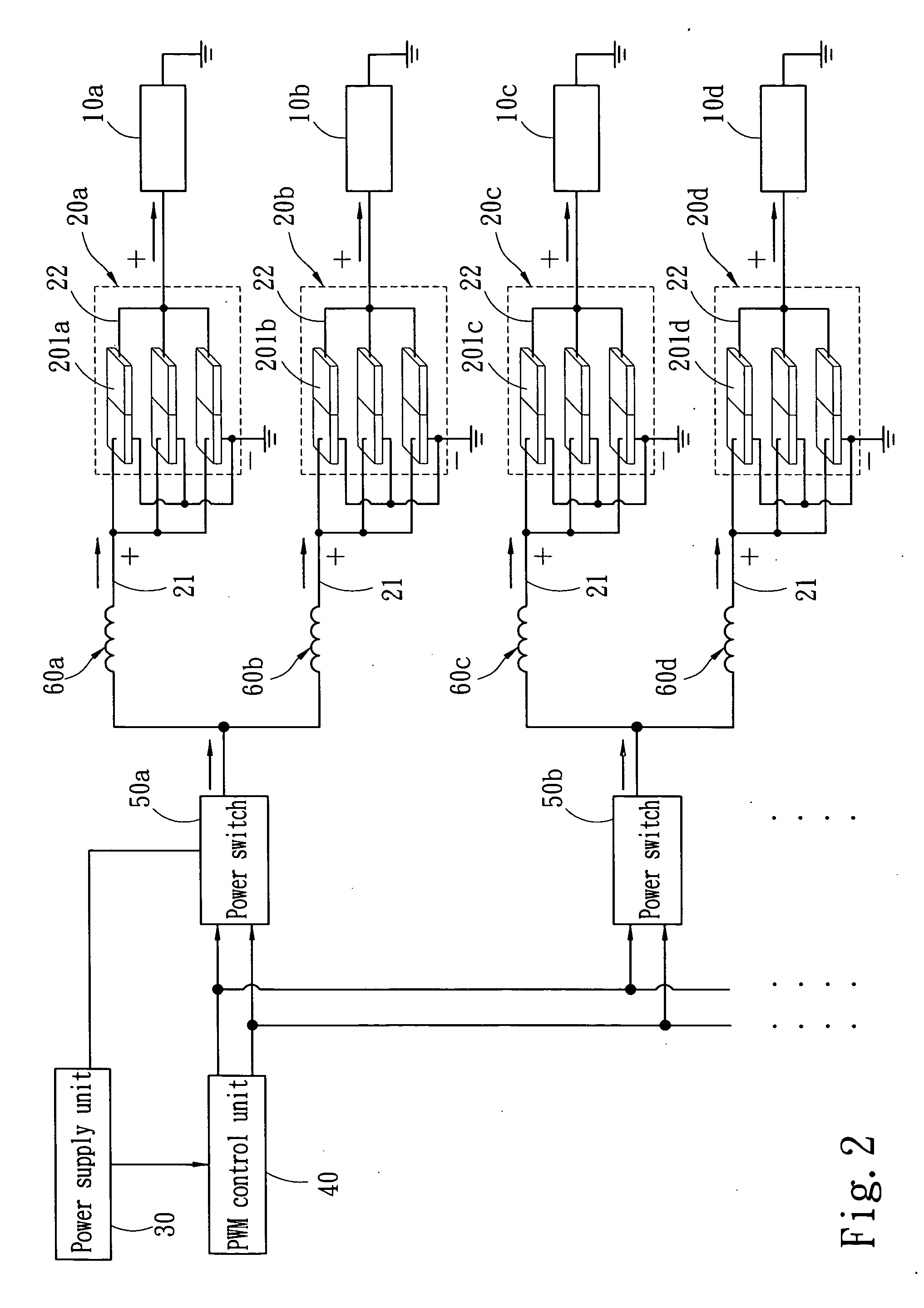
[0020] The embodiments of the invention illustrated below use CCFLs as the loads for detailed discussions.
[0021] Refer to FIG. 1 for the basic circuit topologic diagram of the piezoelectric power supply of the invention to ignite a CCFL 10. It is an AC power supply that is also a pulse-width modulation (PWM) power supply (but not as a limitation). The technique of the PWM power supply is known in the art, details will be omitted. It includes: [0022] a piezoelectric transformer unit 20 which consists of single sheet piezoelectric transformers 201 that have respectively a primary electrode 21 on a first side and a secondary electrode 22 on a second side to transform a high frequency AC signal input from the primary electrode 21 to a high voltage to be output on the secondary electrode 22 to ignite the CCFL 10 connecting to the secondary electrode 22; [0023] a power supply unit 30 to provide an electric power source required to actuate the CCFL 10 (depending on the specification of th...
PUM
 Abstract
Description
Claims
Application Information