High Efficiency rotary piston combustion engine

Inactive Publication Date: 2005-12-27
ELMER BRENT WARREN
View PDF46 Cites 19 Cited by
  • Summary
  • Abstract
  • Description
  • Claims
  • Application Information

AI Technical Summary

Benefits of technology

[0012]In one embodiment of the invention look-up table means are used for providing the control signals based upon the combination of sensor signals from the engine, and requested engine speed and power requirements at any given time. Also, purge valve means are operable for insuring the complete exhaustion of combustion gases from the combustion chamber at the end of a combustion cycle to enhance high speed operation of the rotary engine. The length of the power stroke or power cycle is inversely proportional to the number of combustion cycles within a given period of time. The shorter the power stroke or distance the piston travels between combustion cycles the greater the power output. The efficiency of the engine is maximized through control of the distance the piston travels for each power stroke.

Problems solved by technology

As is well known in the art, typical internal combustion piston engines are highly inefficient during operation.
Various studies have estimated that such operation causes more than fifty percent of the power generated by the combustion of fuel in the engine to be lost.
However, because of the requirement of mechanical timing, and the requirement that exhaust and intake valves are typically mechanically opened and closed, the provision of longer power cycles is very limited, in that the distance a reciprocating piston travels between spark plug ignitions of the fuel / air mixture or between combustion cycles is substantially fixed, in turn, limiting gains in efficiency.

Method used


Image

  • High Efficiency rotary piston combustion engine
  • High Efficiency rotary piston combustion engine
  • High Efficiency rotary piston combustion engine

Examples


Embodiment Construction

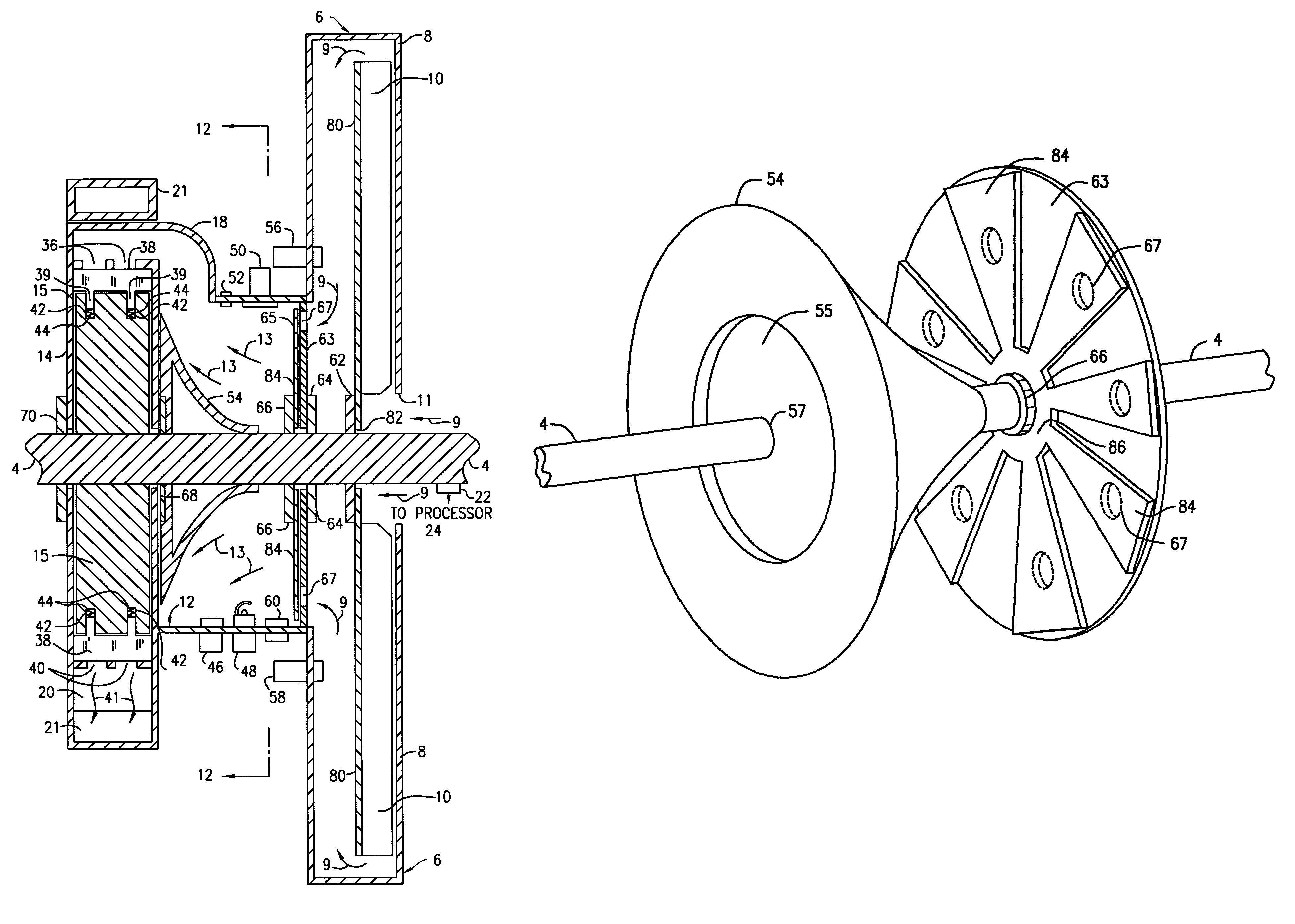
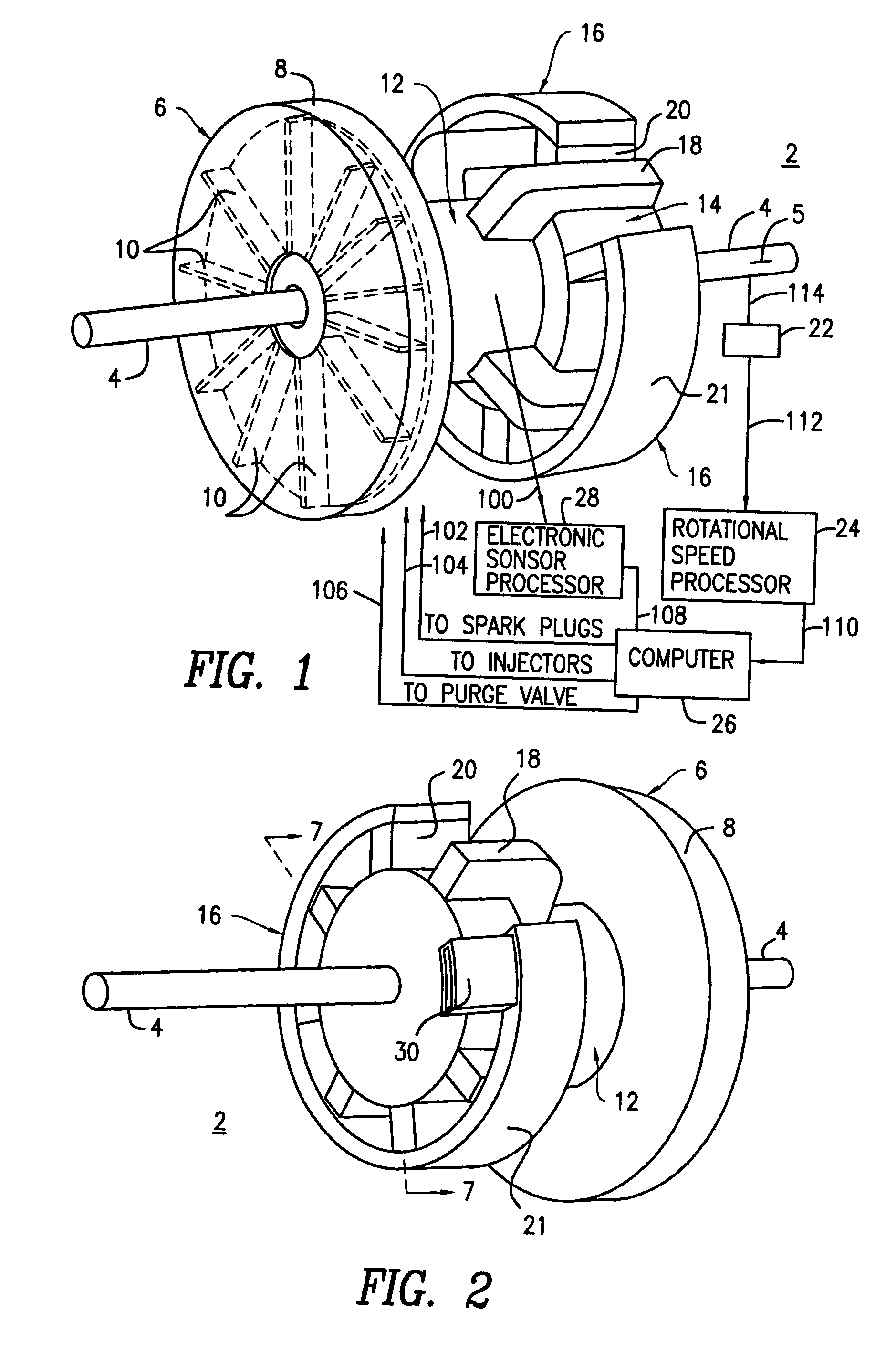
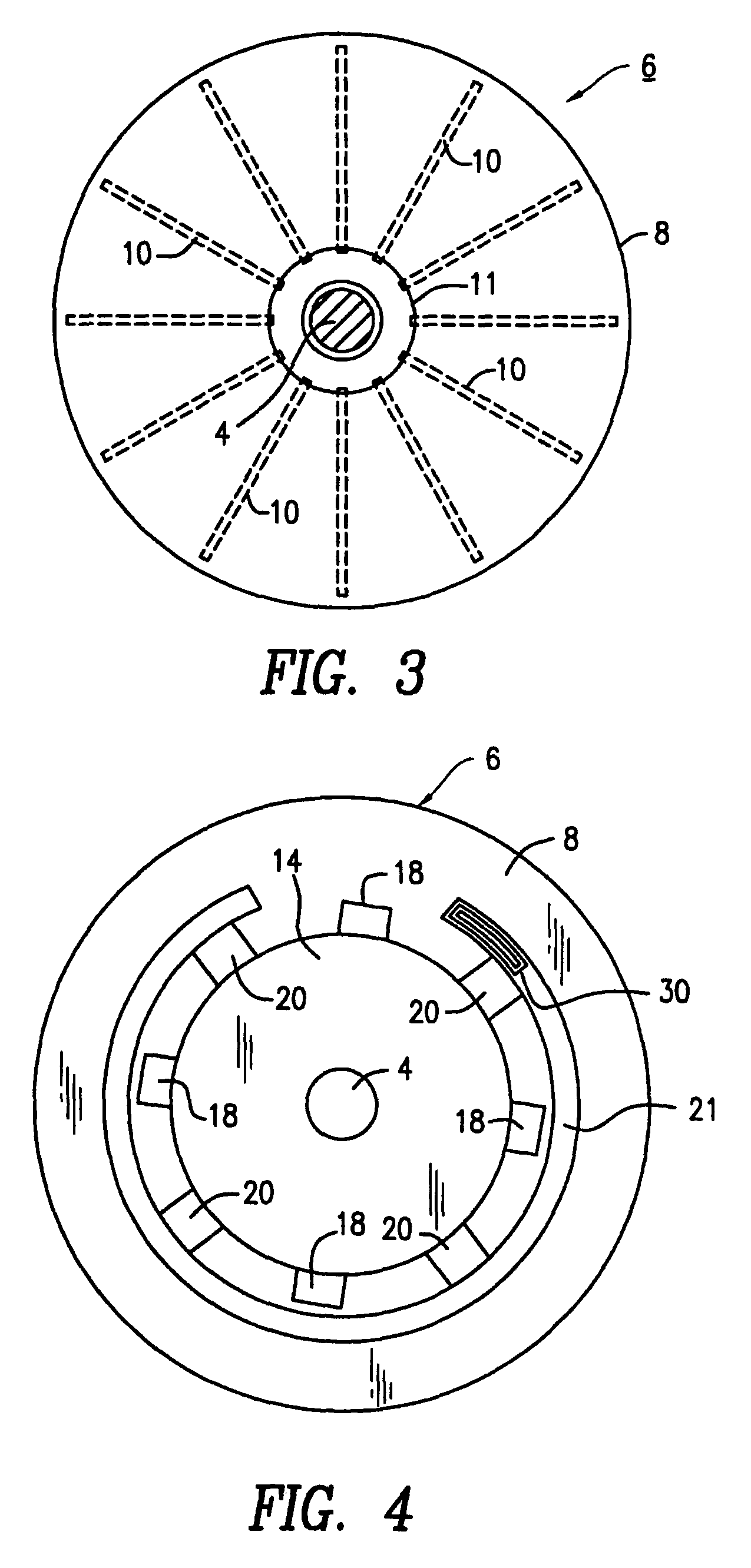
[0035]A pictorial view of the present rotary engine is shown in FIGS. 1 and 2 for a number of embodiments. More particularly, a drive shaft 4 is common to all portions of the rotary engine 2. The front portion of the engine 2 includes a fan or blower 6 that includes a housing 8 substantially enclosing a plurality of spaced apart impeller or fan blades 10, the latter being rigidly connected to a portion of the drive shaft 4, as will be explained in further detail below. As a result, in this embodiment the fan 6 is mechanically driven by drive shaft 4. However, in an alternative embodiment the fan is driven by an electric motor. The fan 6 is connected coaxially to one end of a combustion chamber 12, the other end of which is connected coaxially to a piston chamber 14, in this example. The piston chamber 14 encloses a rotary piston 15 in which a plurality of spring biased vanes 38 are installed. A manifold assembly 16 includes a plurality of equally spaced apart intake manifolds 18 con...


PUM


Abstract

A computer controlled rotary piston engine includes a blower housing containing a rotatable impeller assembly, for pushing ambient air into the housing, and forcing the air to pass through a normally open valve mechanism into a combustion chamber. A plurality of fuel injectors are selectively operable for injecting fuel into the combustion chamber, followed by selective operation of at least one spark plug for igniting the fuel / air mixture, thereby causing the valve mechanism to close, and the combustion gases to pass through a plurality of spaced apart intake manifolds into always open input ports of a piston chamber for rotating a vaned or bladed rotary piston therein, followed by spent combustion gases being forced out of a plurality of spaced always open exhaust ports into an exhaust manifold. The distance the piston travels during a power cycle is adjustable, and inversely proportional to the frequency of combustion or number of combustion cycles within a given period of time.

Description

FIELD OF THE INVENTION[0001]The invention relates generally to internal combustion engines, and more particularly to internal combustion engines that employ a rotary piston that continuously rotates in driving a drive shaft.BACKGROUND OF THE INVENTION[0002]As is well known in the art, typical internal combustion piston engines are highly inefficient during operation. For example, if you end a power cycle for a four cycle engine, the exhaust valve must be held open when its associated piston reaches bottom dead center. Various studies have estimated that such operation causes more than fifty percent of the power generated by the combustion of fuel in the engine to be lost. By providing a longer power cycle for each piston of the engine, it is theoretically possible to improve efficiency. However, because of the requirement of mechanical timing, and the requirement that exhaust and intake valves are typically mechanically opened and closed, the provision of longer power cycles is very...

Claims


Application Information

Patent Timeline
IPC IPC(8): F01C1/344F01C11/00
CPCF01C1/3446F01C11/002
Inventor ELMER, BRENT WARREN
Owner ELMER BRENT WARREN
Why Eureka
Try Eureka