Scene reflectance functions under natural illumination

a natural illumination and reflectance function technology, applied in the field of acquiring and rendering images, can solve the problems of large size of the system that uses controlled incident illumination, large cost, and fixed in the studio, and achieve the effect of efficient estimation of reflectance functions

Inactive Publication Date: 2005-12-29
MITSUBISHI ELECTRIC RES LAB INC
View PDF10 Cites 20 Cited by
  • Summary
  • Abstract
  • Description
  • Claims
  • Application Information

AI Technical Summary

Benefits of technology

[0027] This representation is compact, can be progressively refined, and can determine the relighting of scenes with complex illumination in real-time. The representation and the corresponding method enable efficient estimation of the reflectance functions of scenes with specular, glossy, refractive, and diffuse elements. The method also handles soft and hard shadows, inter-reflections, caustics, and subsurface scattering.

Problems solved by technology

Systems that use controlled incident illumination are usually large, expensive, and fixed in place in studio, even for scenes with small objects.
For large scenes, such as a city, land, or seascape, it is impossible to control the illumination.
However, it is difficult to acquire the 4D reflectance function for arbitrary scenes lit with natural illumination.
This poses a challenge for memory storage.
Moreover, it is necessary to take over a hundred high-resolution images, making the acquisition time prohibitively long.
Consequently, those methods cannot represent high-frequency effects, such as specularities, refraction, and shadows.
However, environment matting methods have difficulty representing hard shadows or a combination of diffuse and specular materials.
However, those methods cannot represent high-frequency phenomena, such as refractions, light discontinuities, or hard shadows.
Furthermore, those methods do not provide progressive refinement of the approximation error with an increasing number of samples.
However, that method requires many wavelet patterns for highly specular and refractive materials, or scenes with hard shadows, e.g., up to 2400 pattern images.
Rendering is also time consuming because the rendering requires a weighted sum of many wavelet-basis images of the new incident illumination.
They use a projector system for scene acquisition and tabulate the results, which limits the sampling resolution.
That method only works off-line and does not progressively refine approximation errors.
Furthermore, only one 2D function is sometimes not expressive enough to capture the properties of complex reflectance functions representing arbitrary scenes under natural illumination, particularly large scenes that can be subject to very complex illumination.
However, rendering with complex incident illumination is slow, because the Gaussian kernels have to be convolved with the new illumination.
Morevover, that method cannot progressively refine the approximation.
In addition, the 2D Gaussian kernels have difficulty representing discontinuous or more complex reflectance functions, such as a small specular lobe inside a larger diffuse component.
In addition, that method uses a number of non-linear optimization steps, which can produce instabilities and noise.
However, that representation is not compact, and that method does not address any of the other problems described above.

Method used


Image

  • Scene reflectance functions under natural illumination
  • Scene reflectance functions under natural illumination
  • Scene reflectance functions under natural illumination

Examples


Embodiment Construction

[0035] System Structure

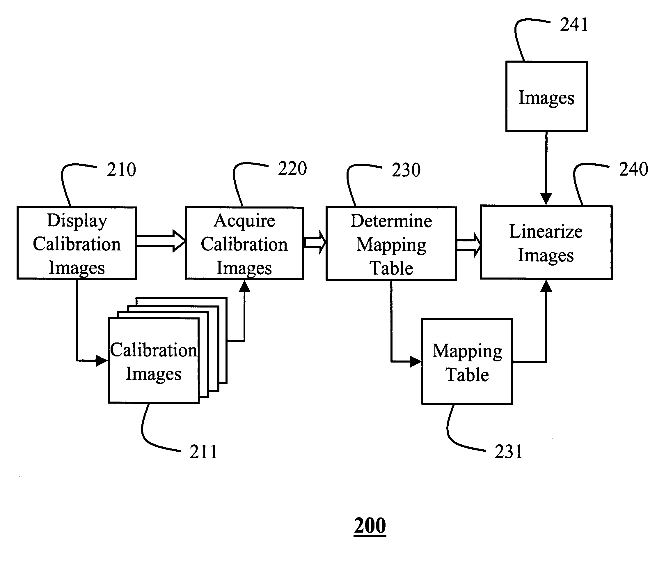
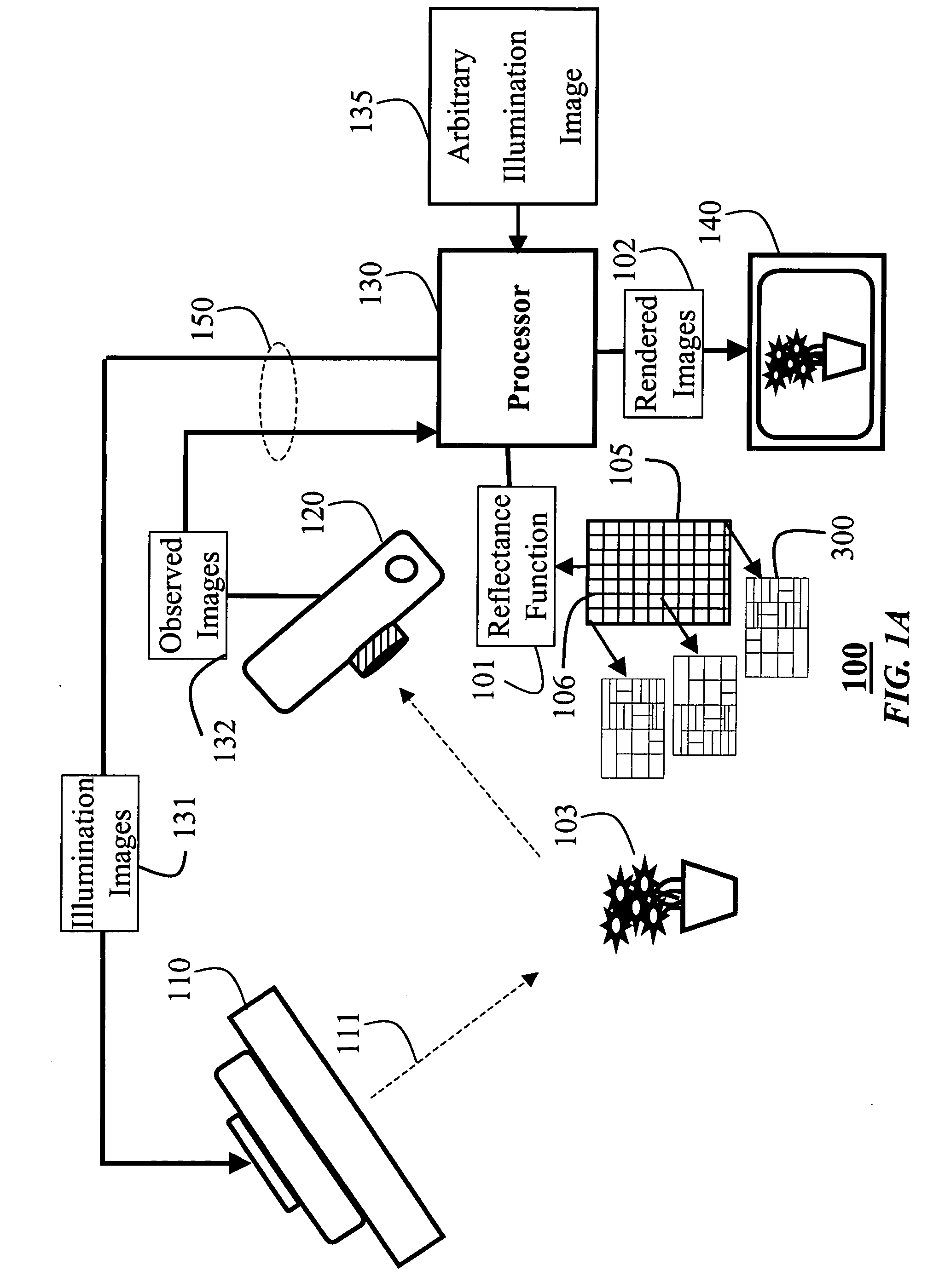
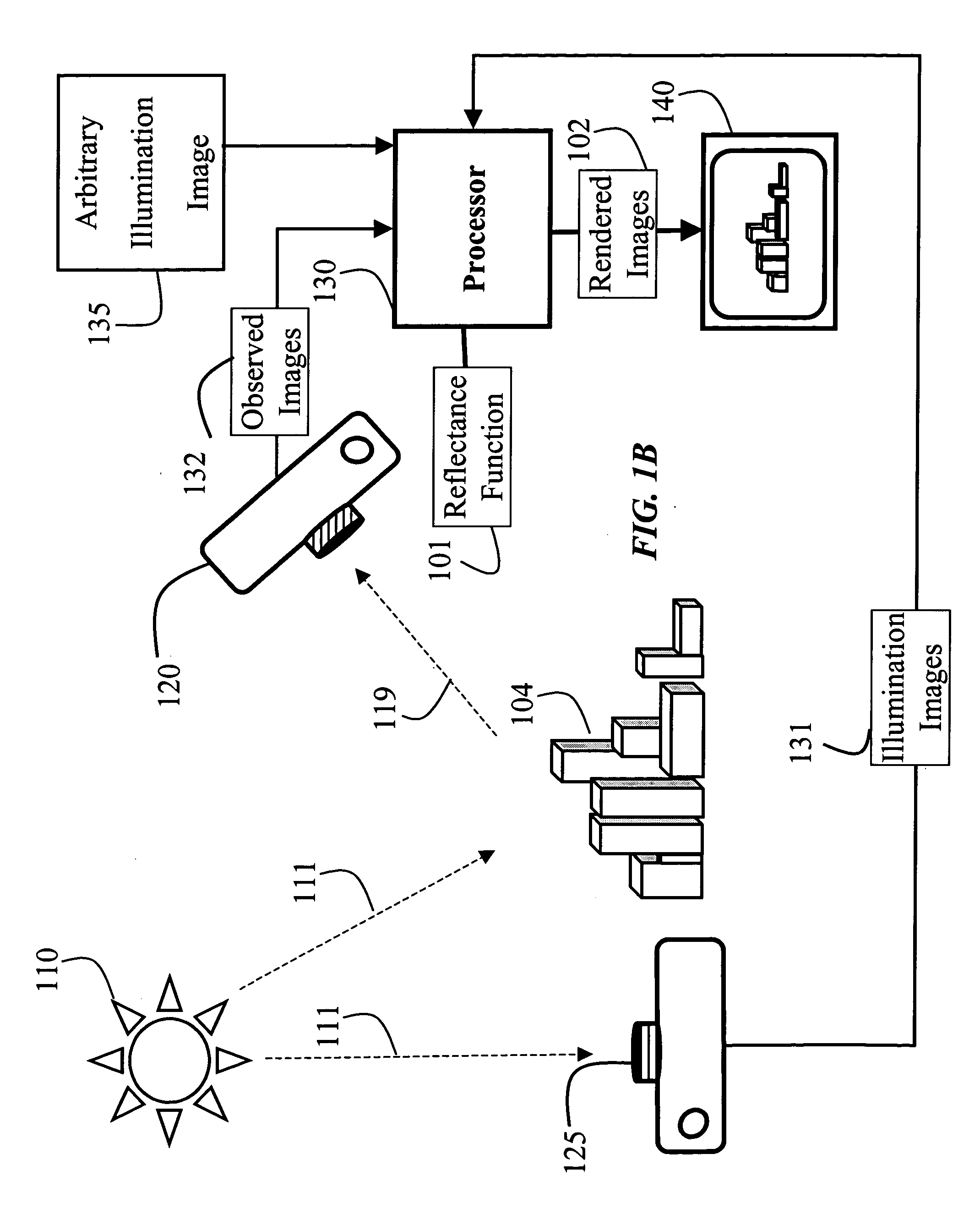
[0036] As shown in FIG. 1, our system 100 for estimating a reflectance function 101 and using the estimated reflectance function to render new images 102 of a scene using arbitrary illumination 135.

[0037] The reflectance function 101 according to the invention is in the form of a reflectance image 105 including a plurality of pixels 106. Each pixel is associated with a set 300 of multiple weighted kernels 301, described in greater detail below.

[0038] The system 100 includes a source 110, e.g., a monitor or artificial or natural light 111 in a surrounding scene, see FIG. 1B, a sensor 120, a processor 130, and an output device 140 for the rendered image 102, all connected by a network. For ‘still-life’ scenes, the scene can include an object 103. The sensor can be a camera. The sensor acquires observed images 132 of the scene subject to the illumination 111.

[0039] The monitor 110 generates high-resolution incident illumination 111 according to illumination i...


PUM


Abstract

A method and system estimates a reflectance function of an arbitrary scene. The scene is illuminated under various lighting condition. For each lighting condition there is an associated illumination image and an observed image. Multiple, non-overlapping kernels are determined for each pixel in a reflectance image from the pairs of illumination and observed images. A weight is then determined for each kernel to estimate the reflectance function represented as the reflectance image.

Description

FIELD OF THE INVENTION [0001] This invention relates generally to acquiring and rendering images, and more particularly to estimating reflectance functions in scenes from natural illumination and rendering images according to the estimated reflectance functions. BACKGROUND OF THE INVENTION [0002] It is desired to acquire images of arbitrary real-world scenes and then to render new or synthetic images of the scene using a reflectance function representing arbitrary natural illumination in the environment. Such a representation has many applications, such as realistic image synthesis, scene analysis, 3D scanning of cultural artifacts, object and face recognition, and relighting of image-based models. [0003] Typical prior art methods require controlled incident illumination, e.g., either a point light source or a structured illumination pattern, and a large number of illumination images. Systems that use controlled incident illumination are usually large, expensive, and fixed in place ...

Claims


Application Information

Patent Timeline
Patent Type & Authority Applications(United States)
IPC IPC(8): G06T7/40G06T15/50
CPCG06T7/40G06T15/506G06T15/50
Inventor PFISTER, HANSPETERMATUSIK, WOJCIECHLOPER, MATTHEW M.
Owner MITSUBISHI ELECTRIC RES LAB INC
Why Eureka
Try Eureka