System and process for generating a two-layer, 3D representation of a scene

a two-layer, 3d representation technology, applied in the field of layered representations of digital or digitized images, can solve the problems of not being able to achieve the goal of allowing users to interactively change to any desired viewpoint, providing significant further complication, and unable to achieve the effect of realizing the goal, so as to prevent cracks

Active Publication Date: 2005-12-29
MICROSOFT TECH LICENSING LLC
View PDF6 Cites 58 Cited by
  • Summary
  • Abstract
  • Description
  • Claims
  • Application Information

AI Technical Summary

Benefits of technology

[0021] This two layer representation is generated by first identifying the location of depth discontinuities in the image under consideration using a disparity map of the image. Depth discontinuities occur at locations where a difference in disparity values between adjacent pixels is more than a prescribed number of levels. The pixels of the image that are found within prescribed sized areas surrounding the depth discontinuities are then identified. The foreground and background colors, along with foreground alpha values, are next estimated for each pixel in these depth discontinuity areas using a matting technique. In addition, foreground and background disparity values are estimated for each pixel in the depth discontinuity areas using alpha-weighted averages of nearby disparities in the foreground and background portions of the image. Then, a boundary layer of the image is established that includes a pixel at each location that corresponds to a pixel of the depth discontinuity areas. The foreground color, foreground disparity and alpha value associated with the corresponding pixel of

Problems solved by technology

Unfortunately, this effect is a one-time, pre-planned affair.
Thus, existing systems would not allow a user to interactively change to any desired viewpoint while watching a dynamic image-based scene.
However, extending IBR to dynamic scenes is not trivial because of the difficulty (and cost) of synchronizing so many cameras as well as acquiring and storing the images.
Not only are there significant hurdles to overcome in capturing, representing, and rendering dynamic scenes from multiple points of view, but being able to do this interactively provides a significant further complication.
To date attempts to realize this goal have not been very satisfactory.
Unfortunately, the results look unrealistic because of low resolution, matching errors, and improper handling of

Method used


Image

  • System and process for generating a two-layer, 3D representation of a scene
  • System and process for generating a two-layer, 3D representation of a scene
  • System and process for generating a two-layer, 3D representation of a scene

Examples


Embodiment Construction

[0028] In the following description of the preferred embodiments of the present invention, reference is made to the accompanying drawings which form a part hereof, and in which is shown by way of illustration specific embodiments in which the invention may be practiced. It is understood that other embodiments may be utilized and structural changes may be made without departing from the scope of the present invention.

1.0 The Computing Environment

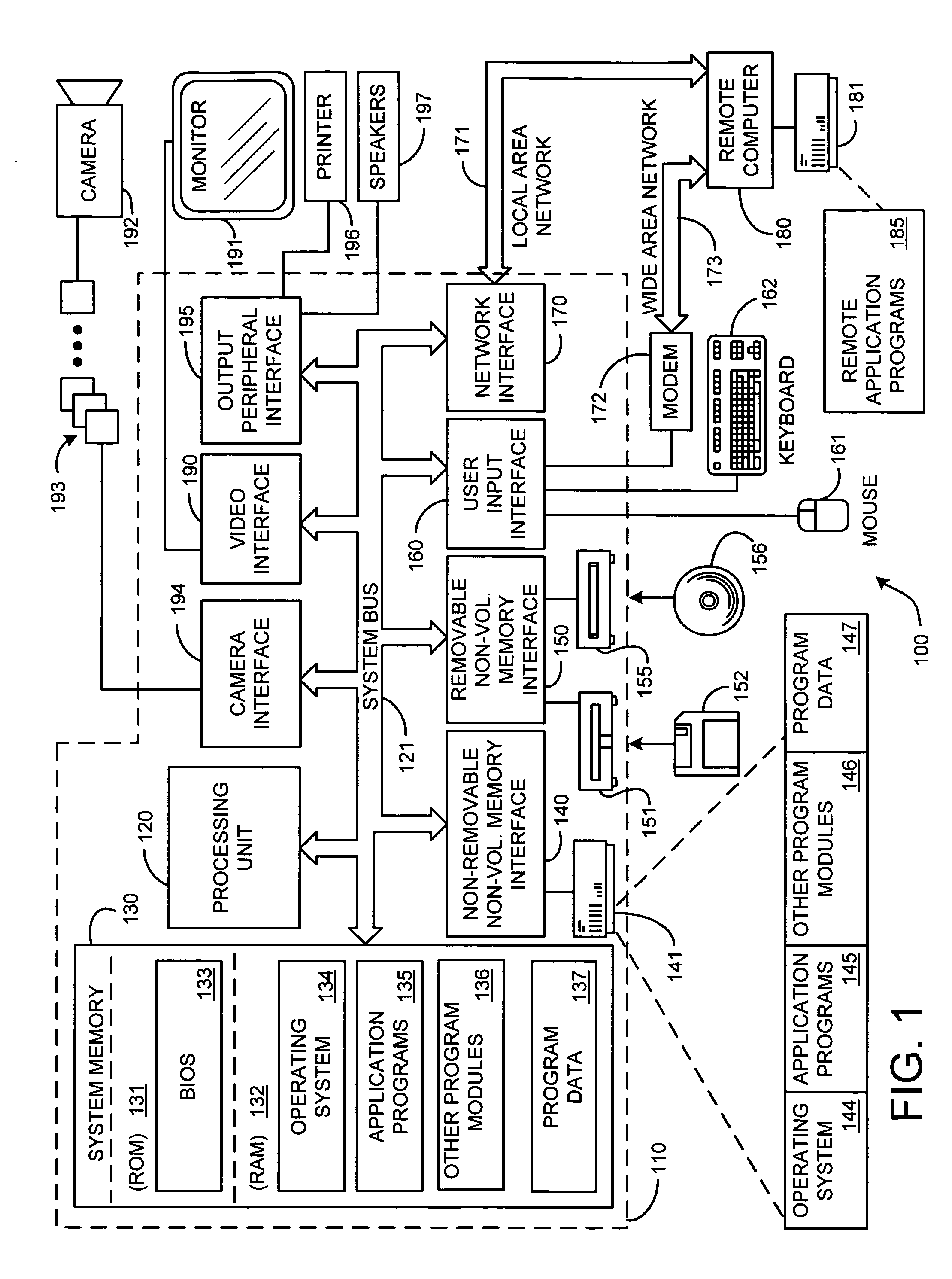
[0029] Before providing a description of the preferred embodiments of the present invention, a brief, general description of a suitable computing environment in which the invention may be implemented will be described. FIG. 1 illustrates an example of a suitable computing system environment 100. The computing system environment 100 is only one example of a suitable computing environment and is not intended to suggest any limitation as to the scope of use or functionality of the invention. Neither should the computing environment 100 be inte...


PUM


Abstract

A system and process for generating a two-layer, 3D representation of a digital or digitized image from the image and a pixel disparity map of the image is presented. The two layer representation includes a main layer having pixels exhibiting background colors and background disparities associated with correspondingly located pixels of depth discontinuity areas in the image, as well as pixels exhibiting colors and disparities associated with correspondingly located pixels of the image not found in these depth discontinuity areas. The other layer is a boundary layer made up of pixels exhibiting foreground colors, foreground disparities and alpha values associated with the correspondingly located pixels of the depth discontinuity areas. The depth discontinuity areas correspond to prescribed sized areas surrounding depth discontinuities found in the image using a disparity map thereof.

Description

BACKGROUND [0001] 1. Technical Field [0002] The invention is related to layered representations of digital or digitized images, and more particularly to a system and process for generating a two-layer, 3D representation of a scene. [0003] 2. Background Art [0004] For several years now, viewers of TV commercials and feature films have been seeing the “freeze frame” effect used to create the illusion of stopping time and changing the camera viewpoint. The earliest commercials were produced by using a film-based system, which rapidly jumped between different still cameras arrayed along a rail to give the illusion of moving through a frozen slice of time. [0005] When it first appeared, the effect was fresh and looked spectacular, and soon it was being emulated in many productions, the most famous of which is probably the “bullet time” effects seen in the movie entitled “The Matrix”. Unfortunately, this effect is a one-time, pre-planned affair. The viewpoint trajectory is planned ahead o...

Claims


Application Information

Patent Timeline
IPC IPC(8): G06T13/00G06T15/10G06T15/70G09G5/02
CPCG06T15/205G06T15/00G06T1/00
Inventor ZITNICK, CHARLES LAWRENCE IIISZELISKI, RICHARDKANG, SING BINGUYTTENDAELE, MATTHEW T.WINDER, SIMON
Owner MICROSOFT TECH LICENSING LLC
Why Eureka
Try Eureka