Low frequency transcutaneous energy transfer to implanted medical device

a low-frequency, medical device technology, applied in the field of medical implantable devices, can solve the problems of inability to function at all, device performance erratically or not at all, and inability to achieve any effect on the output power supplied to the implanted device, so as to avoid heating, avoid excessive power loss, and penetrate the physical boundary efficiently.

Inactive Publication Date: 2005-12-29
ETHICON ENDO SURGERY INC
View PDF54 Cites 269 Cited by
  • Summary
  • Abstract
  • Description
  • Claims
  • Application Information

AI Technical Summary

Benefits of technology

[0016] The invention overcomes the above-noted and other deficiencies of the prior art by providing a transcutaneous energy transfer (TET) system that advantageously transmits between 1 to 100 kHz, thereby achieving

Problems solved by technology

Variations in the spacing can cause changes in the AC magnetic field strength reaching the secondary coil, in turn causing power fluctuations and surges in the implant device.
Variations in the supplied power, such as sudden changes in voltage or current levels, may cause the device to perform erratically or fail to function at all.
Accordingly, one issue associated with conventional TET systems is that the physical displacement of either the primary or secondary coils from an optimum coupling position may cause an unacceptable effect on the output power supplied to the implanted device.
While effective, it is desirable to avoid having to adjust the fluid volume with a syringe needle since an increased risk of infection may result, as well as inconvenience and discomfort to the patient.
Moreover, these devices may remain unpowered between adjustments, which provides additional advantages such as not requiring a battery.
This parasitic coupling produces eddy currents in the implan

Method used


Image

  • Low frequency transcutaneous energy transfer to implanted medical device
  • Low frequency transcutaneous energy transfer to implanted medical device
  • Low frequency transcutaneous energy transfer to implanted medical device

Examples


Embodiment Construction

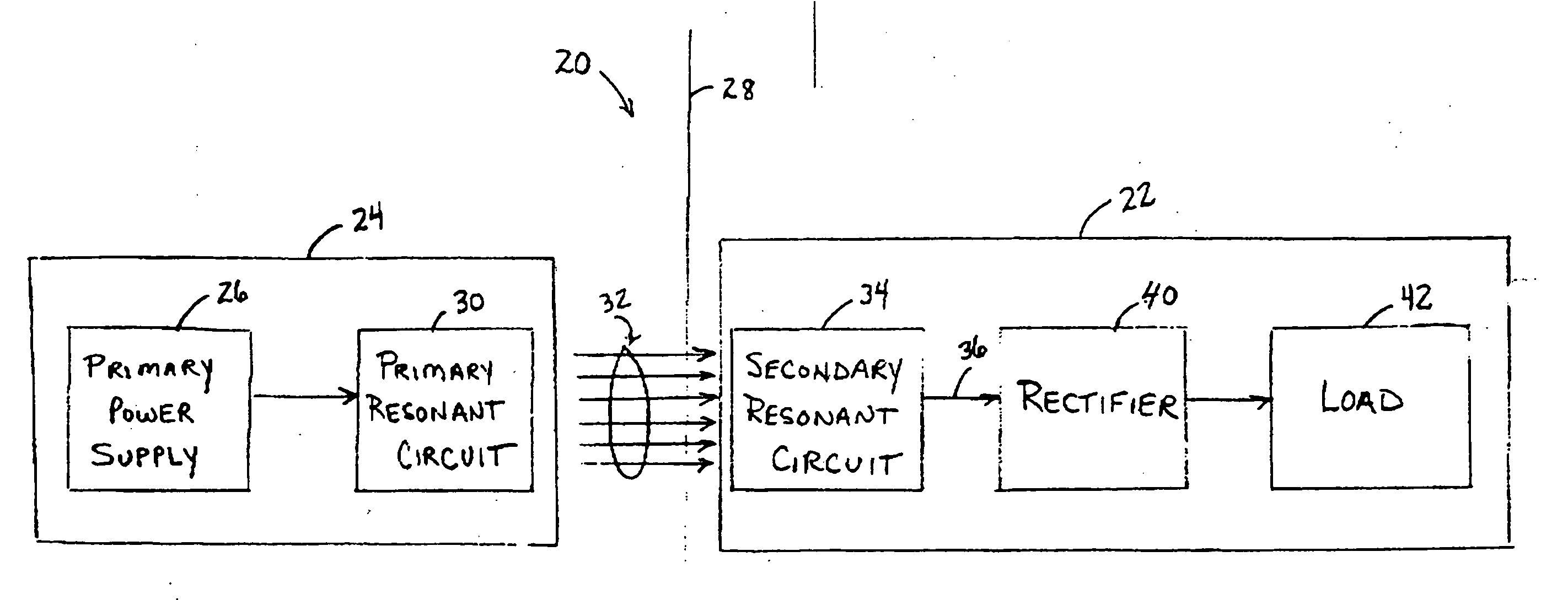
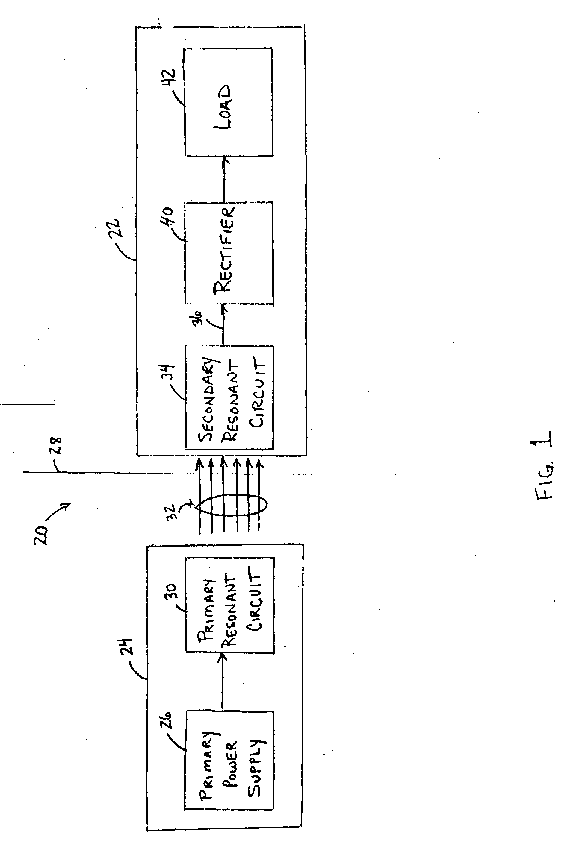
[0024] Referring now to the drawings in detail, wherein like numerals indicate the same elements throughout the views, FIG. 1 depicts the relationship between a transcutaneous energy transfer (TET) system 20 for an implant device 22 in accordance with the present invention. As shown in FIG. 1, TET system 20 includes a primary circuit 24 comprising a power supply 26 located external to a physical boundary 28. Boundary 28 may be the skin of a human or animal body, such as in the case of a medical implant, or may be any other type of inanimate material or tissue depending upon the particular application of TET system 20. Primary circuit 24 also includes a primary resonant circuit 30 that is electrically coupled to power supply 26 to resonate at a designated power signal frequency. An alternating magnetic field 32 is generated in primary coil 30 in response to an electrical signal provided by power supply 26.

[0025] TET system 20 also includes a secondary resonant circuit 34 in a spaced...


PUM


Abstract

An implantable medical device system advantageously utilizes low frequency (e.g., about 1-100 kHz) transcutaneous energy transfer (TET) for supplying power from an external control module to an implantable medical device, avoiding power dissipation through eddy currents in a metallic case of an implant and/or in human tissue, thereby enabling smaller implants using a metallic case such as titanium and/or allowing TET signals of greater strength thereby allowing placement more deeply within a patient without excessive power transfer inefficiencies.

Description

CROSS REFERENCE TO RELATED APPLICATIONS [0001] The present application is related to four co-pending and commonly-owned applications filed on even date herewith, the disclosure of each being hereby incorporated by reference in their entirety, entitled respectively: [0002]“TRANSCUTANEOUS ENERGY TRANSFER PRIMARY COIL WITH A HIGH ASPECT FERRITE CORE” to James Giordano, Daniel F. Dlugos, Jr. & William L. Hassler, Jr., Ser. No. ______; [0003]“MEDICAL IMPLANT HAVING CLOSED LOOP TRANSCUTANEOUS ENERGY TRANSFER (TET) POWER TRANSFER REGULATION CIRCUITRY” to William L. Hassler, Jr., Ed Bloom, Ser. No. ______; [0004]“MAGNETIC RESONANCE IMAGING (MRI) COMPATIBLE REMOTELY ADJUSTABLE GASTRIC BAND”, to William L. Hassler, Jr. et al., Ser. No. ______; [0005]“SPATIALLY DECOUPLED TWIN SECONDARY COILS FOR OPTIMIZING TRANSCUTANEOUS ENERGY TRANSFER (TET) POWER TRANSFER CHARACTERISTICS” to Resha H. Desai, William L. Hassler, Jr., Ser. No. ______; and [0006]“LOW FREQUENCY TRANSCUTANEOUS TELEMETRY TO IMPLANT...

Claims


Application Information

Patent Timeline
IPC IPC(8): A61N1/08A61N1/32A61N1/372A61N1/378
CPCA61N1/3787A61N1/37223A61F2/0036A61F5/0059A61F2250/0001
Inventor HASSLER, WILLIAM L. JR.DLUGOS, DANIEL F. JR.
Owner ETHICON ENDO SURGERY INC
Why Eureka
Try Eureka