Ultrasonic liquid flow controller

a liquid flow controller and ultrasonic technology, applied in the direction of machines/engines, process and machine control, instruments, etc., can solve the problems of substantial surface irregularities, photolithographic steps, and surface irregularities that have become serious problems

Active Publication Date: 2005-12-29
BROOKS INSTRUMENT
View PDF45 Cites 98 Cited by
  • Summary
  • Abstract
  • Description
  • Claims
  • Application Information

AI Technical Summary

Problems solved by technology

As the level of integration on semiconductor wafers increases, surface irregularities have become a serious problem.
For example, metallization layers used to form interconnects between the various devices on a wafer may lead to substantial surface irregularities that may interfere with subsequent photolithographic steps.
A significant disadvantage of conventional planarization systems is that the planarization fluid cannot be mixed close to where (and when) it will be used.
Conventional flow meters and flow controllers lack the accuracy often needed to implement point-of-use mixing of planarization fluids.

Method used


Image

  • Ultrasonic liquid flow controller
  • Ultrasonic liquid flow controller
  • Ultrasonic liquid flow controller

Examples


Embodiment Construction

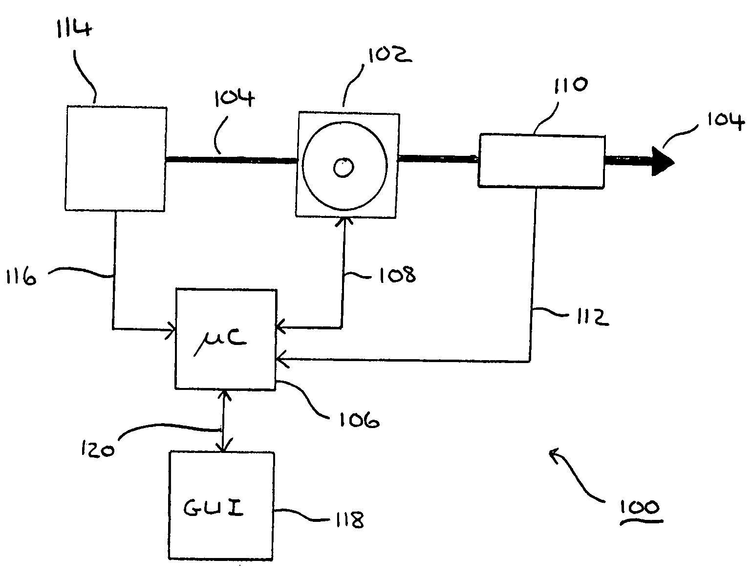
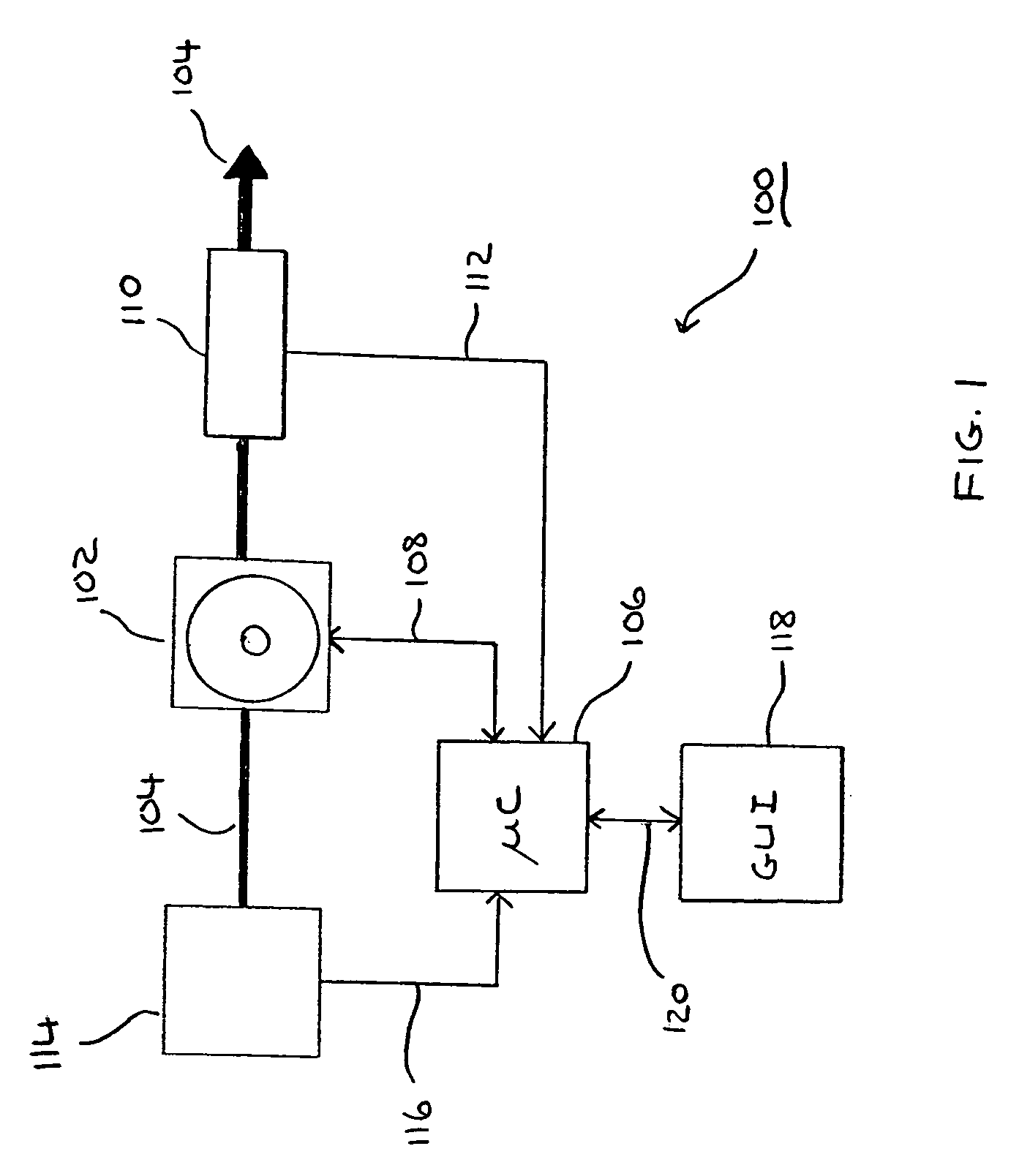
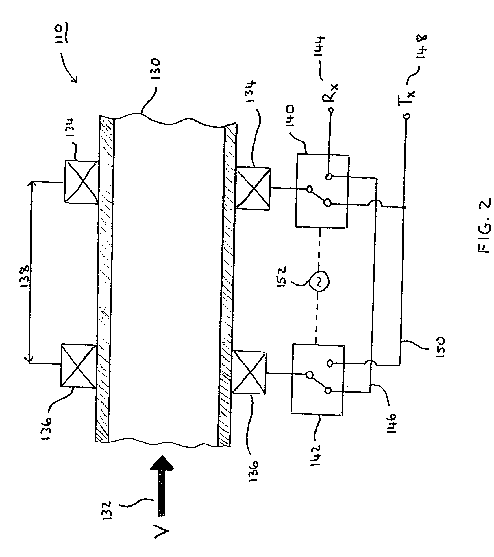
[0028] Various embodiments and aspects thereof will now be discussed in detail with reference to the accompanying figures. It is to be appreciated that this invention is not limited in its application to the details of construction and the arrangement of components set forth in the following description or illustrated in the drawings. The invention is capable of other embodiments and of being practiced or of being carried out in various ways. Examples of specific implementations are provided herein for illustrative purposes only. In particular, acts, elements and features discussed in connection with one embodiment are not intended to be excluded from a similar role in other embodiments. Also, the phraseology and terminology used herein is for the purpose of description and should not be regarded as limiting. The use of “including,”“comprising,” or “having,”“containing,”“involving,” and variations thereof herein, is meant to encompass the items listed thereafter and equivalents ther...


PUM


Abstract

An ultrasonic flow meter includes a conduit, a first ultrasonic transducer, a second ultrasonic transducer, and a controller. The first ultrasonic transducer is disposed at a first position about a first portion of the conduit to transmit a first ultrasonic signal and to receive a second ultrasonic signal. The second ultrasonic transducer is disposed at a second position about a second portion of the conduit that is spaced apart from the first position along a length of the conduit to transmit the second ultrasonic signal and to receive the first ultrasonic signal. The controller is configured to cross-correlate the first and second received ultrasonic signals and generate a resulting time-domain signal, analyze the resulting time-domain signal to determine a difference in transit time between the first and second received ultrasonic signals, and calculate a rate of flow of a fluid in the conduit based upon the determined difference.

Description

BACKGROUND [0001] 1. Field of the Invention [0002] The present invention relates to liquid flow controllers and more particularly to an ultrasonic liquid flow meter that may be used in a liquid flow controller. [0003] 2. Discussion of Related Art [0004] Various prior art techniques for measuring a flow rate of a fluid, such as a liquid or gas, flowing in a conduit, for example, a pipe or tube, are known, including thermal flow meters, coriolis force flow meters, and differential pressure flow meters. It is also known to incorporate these and other types of flow meters in feedback control loops so as to control the flow of a fluid in a system. [0005] During manufacture of semiconductor devices, many different fluids must be precisely and accurately dispensed for use on a wafer surface being treated. For example, in a conventional apparatus, the wafers to be treated are typically positioned beneath a nozzle that then dispenses a predetermined amount of fluid (e.g., water, slurry, etch...

Claims


Application Information

Patent Timeline
Patent Type & Authority Applications(United States)
IPC IPC(8): G01F1/00G01F1/66
CPCG01F1/66G05D7/0635G01F1/667Y10T137/7761
Inventor URDANETA, NELSONTINT, AARON S.DUAN, HAOREDEMANN, ERIC J.WACINSKI, CHRISTOPHER ANDREW
Owner BROOKS INSTRUMENT
Why Eureka
Try Eureka