High energy ignition method and system using pre-dwell control

a high-energy, pre-dwell control technology, applied in the direction of electric ignition installation, machines/engines, mechanical equipment, etc., can solve the problems of traction control devices being forbidden in most high-speed racing applications, unable to fire spark plugs, and residual energy typically remaining in the ignition coil, so as to achieve efficient energy storage and performance, and reduce speed

Inactive Publication Date: 2006-01-05
MSD LLC
View PDF44 Cites 22 Cited by
  • Summary
  • Abstract
  • Description
  • Claims
  • Application Information

AI Technical Summary

Problems solved by technology

However, at high speeds, residual energy typically remains stored in the ignition coil even after the spark is discharged.
Since distributor-based systems only have a single coil, they can only fire the spark plugs every 90 degrees of crankshaft rotation.
Although valuable in normal passenger driver applications, traction control devices are forbidden in most high-speed racing applications, since they give an unfair advantage to drivers employing these devices.
Previous distributor-based, single ignition coil systems are incapable of effectively managing the energy stored in the ignition coil for all speeds of the engine using dwell control.
When dwell control was attempted at all, it was made imprecisely and / or was incapable of controlling a high current ignition coil with low inductance and high energy storage and low power dissipation at high power levels under all operating conditions.
Consequently, these previous systems could not effectively manage the stored energy or residual energy of the coil at lower speeds and, at the same time, provide the full stored energy needed by the engine at higher speeds.
Undesirable consequences often occurred in previous systems, for instance, the burning out the ignition coil at some speeds and the inability to provide the proper energy at other speeds of operation.

Method used


Image

  • High energy ignition method and system using pre-dwell control
  • High energy ignition method and system using pre-dwell control
  • High energy ignition method and system using pre-dwell control

Examples


Embodiment Construction

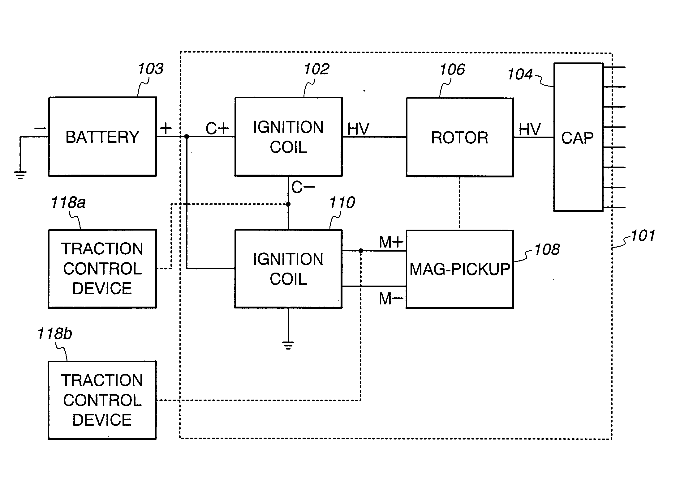
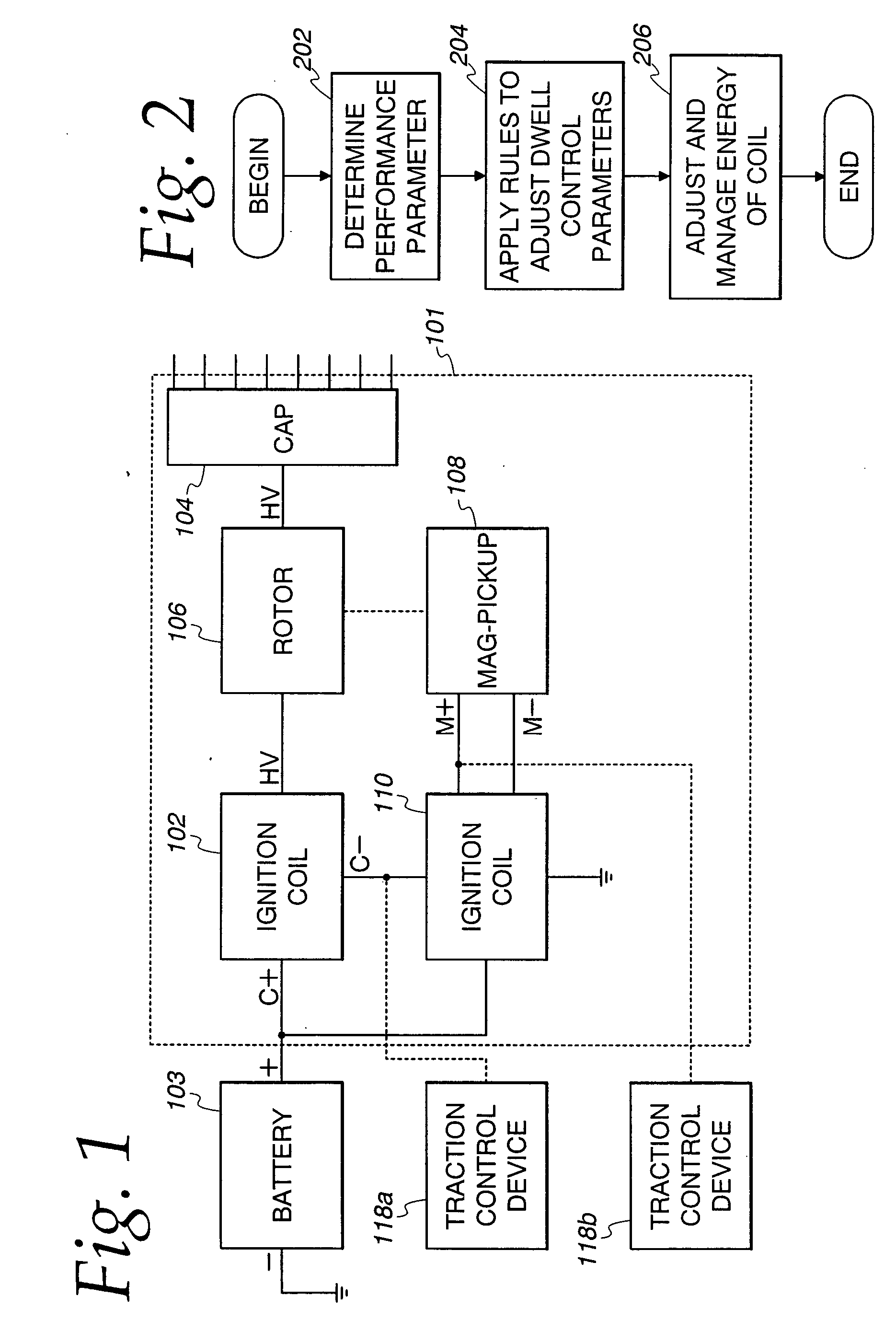
[0040] Referring now to FIG. 1, a system for adjusting the dwell control parameters (including predwell parameters) includes a distributor 101 includes a single ignition coil 102, a distributor cap 104, a rotor 106, a mag-pickup 108 (providing a mag-input signal M+ and M−), and an ignition control module 110. Optionally, a traction control device 118a and 118b may be coupled to the ignition coil 102 or ignition control 110 as shown. The distributor cap 104 is coupled to the spark plugs of the cylinders of the engine. A battery 103 supplies current to the ignition coil 102.

[0041] The present approach overcomes the problems of previous systems by not using excess current dwell at peak current. By not using excess current dwell, the power dissipation in the ignition electronics of the ignition control 110 and the ignition coil 102 is reduced substantially. The current in the primary of coil 102 is controlled at optimum current levels over a wide range of engine speed and engine load c...


PUM


Abstract

A system and method of managing the energy stored in a single ignition coil of a distributor inductive ignition for an engine. The engine comprises a plurality of cylinders and the ignition coil has a primary coil current. The ignition coil has a stored energy and a released energy during an ignition period. A pre-dwell time period and a pre-dwell current level is determined. The stored energy of the ignition coil and the released energy of the ignition coil are balanced during the ignition period at least in part by dwelling the primary coil current in the ignition coil at substantially the pre-dwell current level.

Description

CROSS-REFERENCES To RELATED APPLICATION [0001] This application is a continuation-in-part application of U.S. application Ser. No. 10 / 723,068, filed on Nov.26, 2003, which is incorporated herein by reference in its entirety.FIELD OF THE INVENTION [0002] The field of the invention relates to engine control systems for motor vehicles and more particularly to high energy ignition control systems for motor vehicles. BACKGROUND OF THE INVENTION [0003] An internal combustion engine operates when sparks are applied by spark plugs to a homogenous air and fuel mixture in the combustion chambers of the engine. After application of the spark to the mixture in the combustion chambers, the sparks ignite the mixture, causing the engine to rotate the crank shaft of the engine. The spark energy is generated by an ignition coil and the time that the current is applied to the ignition coil primary is usually referred to as the dwell or on-time of the ignition coil primary. [0004] Ignition systems may...

Claims


Application Information

Patent Timeline
Patent Type & Authority Applications(United States)
IPC IPC(8): F02P9/00F02P5/00
CPCF02P3/0456Y02T10/46F02P5/1555F02P5/1502Y02T10/40
Inventor MASTERS, STEPHEN C.WAITS, DOUGLAS B.
Owner MSD LLC
Why Eureka
Try Eureka