Air conditioner for vehicle

a technology for air conditioners and vehicles, applied in vehicle components, vehicle heating/cooling devices, transportation and packaging, etc., can solve the problems of large installation space of air conditioners, delay in temperature change time, and substantial reduction of cooling and heating efficiency of rear seats, etc., to achieve rapid temperature control

Active Publication Date: 2006-01-05
HANON SYST
View PDF2 Cites 20 Cited by
  • Summary
  • Abstract
  • Description
  • Claims
  • Application Information

AI Technical Summary

Benefits of technology

[0012] Accordingly, the present invention has been made in view of the above-mentioned problems occurring in the prior art, and further, an object of the present invention is to provide a multi-zone type air conditioner for a vehicle that enables a rapid temperature control, and can independently control the temperature of front and rear areas and left and right areas inside the vehicle.

Problems solved by technology

In the conventional air conditioner for the vehicle, however, vent outlets and floor outlets that supply the air from the air conditioner to the interior of the vehicle are disposed on the front sides of the front seats, which makes the cooling and heating efficiencies for the rear seats substantially low.
According to the prior art, however, the control of temperature of the air from the air conditioner is made by permitting or stopping the supply of the working fluids such that because of the continuously flowing characteristic of the fluid the temperature of air from the air conditioner is not rapidly changed in response to the manipulation of a user, thereby inevitably causing the delay of time for the temperature change.
This causes the whole installation space of the air conditioner to be bulky and makes the number of working processes and the manufacturing cost due to the increase of the number of parts substantially raised.

Method used


Image

  • Air conditioner for vehicle
  • Air conditioner for vehicle
  • Air conditioner for vehicle

Examples


Embodiment Construction

[0028] Reference will now be made in detail to the preferred embodiments of the present invention, examples of which are illustrated in the accompanying drawings.

[0029] According to the present invention, an air conditioner for a vehicle includes a front seat air conditioning unit and a rear seat air conditioning unit, and an explanation of each of them is given below.

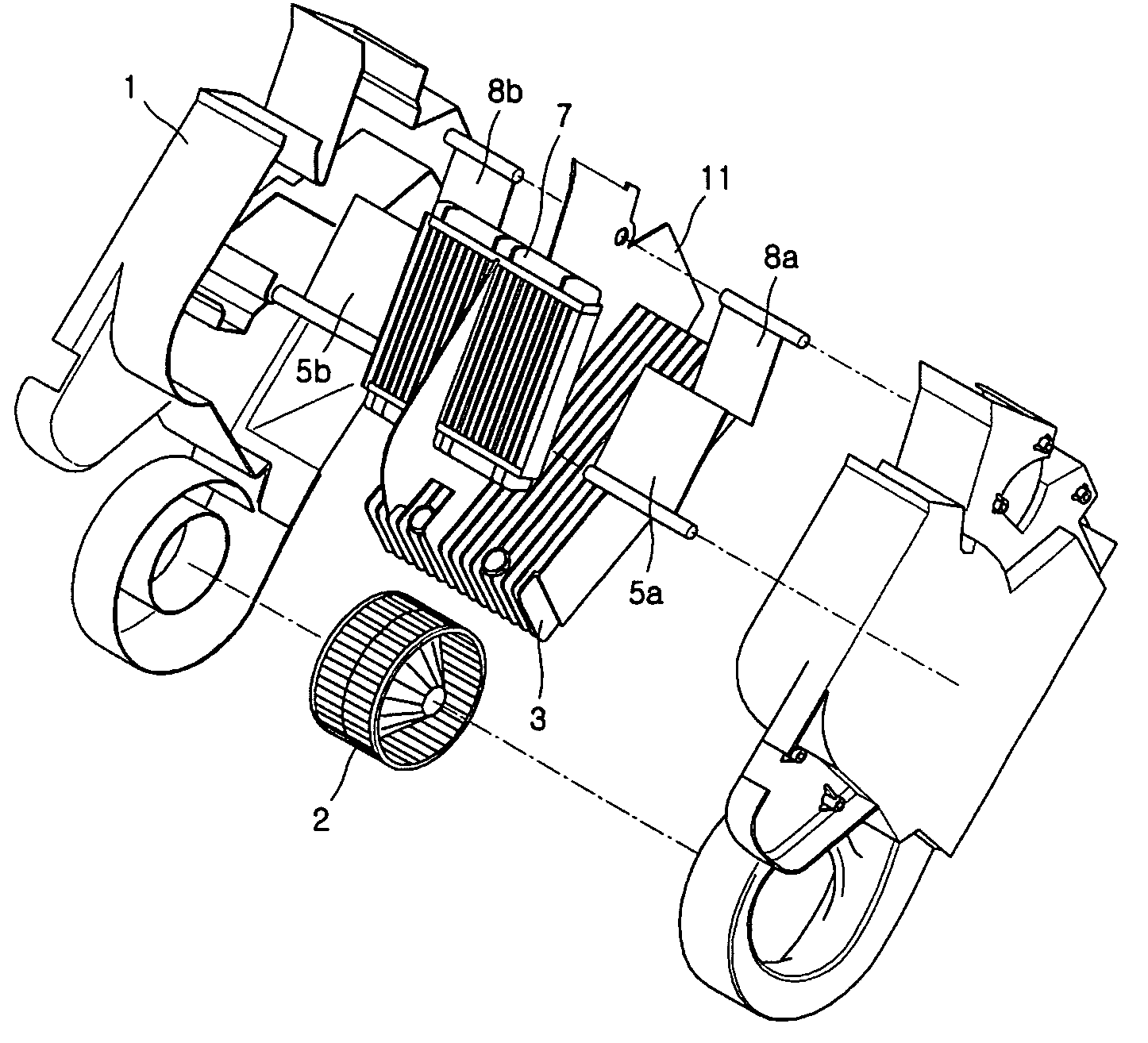
[0030]FIG. 3 is a sectional view of showing a front seat air conditioning unit constructed according to an embodiment of the present invention. As shown, a front seat air conditioning unit 200 includes a front seat air conditioning casing 21 in which a plurality of air flow passages are arranged, a front seat blower 22 disposed in the front seat air conditioning casing 21, a front seat evaporator 23 and a front seat heater core 27 for cooling and heating the internal and external air in / from the air conditioner, and front seat mode doors 30a and 30b for opening and closing the outlets 126a, 126b, 129a, 129b, 130a, an...


PUM


Abstract

The present invention relates to an air conditioner for vehicle including a front seat air conditioning unit and a rear seat air conditioning unit. The rear seat air conditioning unit has a rear seat air conditioning casing provided with a rear seat evaporator disposed in generally horizontal direction to air flow passages therein, with a rear seat heater core disposed over the rear seat evaporator, with vent outlets and floor outlets disposed on the upper and lower portions of the exit end thereof for discharging the air flowing from the air conditioner to the rear seats of the vehicle, with a rear seat partition wall adapted to divide the air flow passages into two areas, with rear seat temperature doors disposed between the rear seat evaporator and the rear seat heater core, for adjusting the temperatures of the divided areas by the rear seat partition wall, with rear seat mode doors disposed adjacent to the vent outlets and the floor outlets for controlling the degree of opening of the vent outlets and the floor outlets, and with a rear seat blower housed at one side thereof for blowing the air to the rear seat air conditioning casing.

Description

BACKGROUND OF THE INVENTION [0001] 1. Field of the Invention [0002] The present invention relates to an air conditioner for a vehicle that is used to conduct heating and cooling for front and rear seats inside the vehicle, and more particularly, to a multi-zone type air conditioner for a vehicle that enables a rapid temperature control, and can independently control the temperature of front and rear areas and left and right areas inside the vehicle. [0003] 2. Background of the Related Art [0004] Typically, a vehicle is provided with an air conditioner that heats or cools internal and external air to supply or circulate the heated or cooled air to the interior thereof, thereby keeping the air inside the vehicle at an appropriate temperature and making occupants inside the vehicle feel good. The air conditioner generally includes a casing in which a plurality of air flow passages are formed therein, a blower disposed at one side of the casing for absorbing the internal and external ai...

Claims


Application Information

Patent Timeline
Patent Type & Authority Applications(United States)
IPC IPC(8): B60H1/00B60H1/12B60H1/34
CPCB60H1/00064B60H1/00207B60H2001/002B60H2001/00135B60H2001/00192B60H2001/00107B60H1/00B60H1/12B60H1/34
Inventor KANG, SUNGHOBYON, SANGCHULSEO, YONGEUNKIM, YONGSANG
Owner HANON SYST
Why Eureka
Try Eureka