Billet support system for induction heating

a technology of induction heating and support system, which is applied in the direction of work heating device, furniture, lighting and heating apparatus, etc., can solve the problems of inability to apply the support of the billet, short circuit of the induction coil, and material wear

Active Publication Date: 2006-01-05
INDUCTOTHERM INDS
View PDF8 Cites 17 Cited by
  • Summary
  • Abstract
  • Description
  • Claims
  • Application Information

AI Technical Summary

Problems solved by technology

In the third method the billet is externally supported while a portion (such as the center or an end) of the billet is inductively heated; this method is not applicable to billet support when the billet length is shorter than the coil.
Over time the rod material wears away and portions of the internal cooling passages leak water, which can cause electrical short circuits in the induction coil.
Further the necessity of making water connections to the rods inhibits repositioning of the rods to better accommodate billets of varying sizes.

Method used


Image

  • Billet support system for induction heating
  • Billet support system for induction heating
  • Billet support system for induction heating

Examples


Embodiment Construction

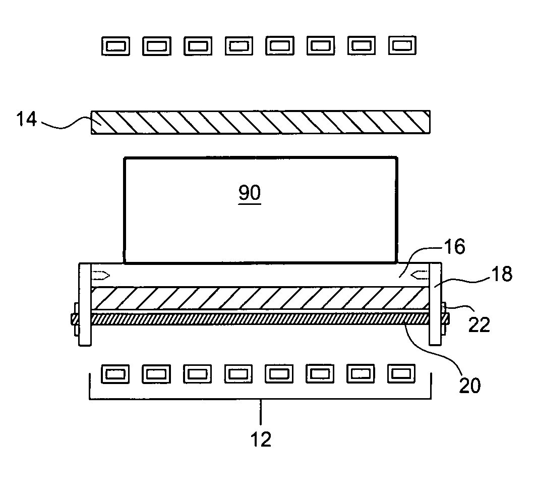
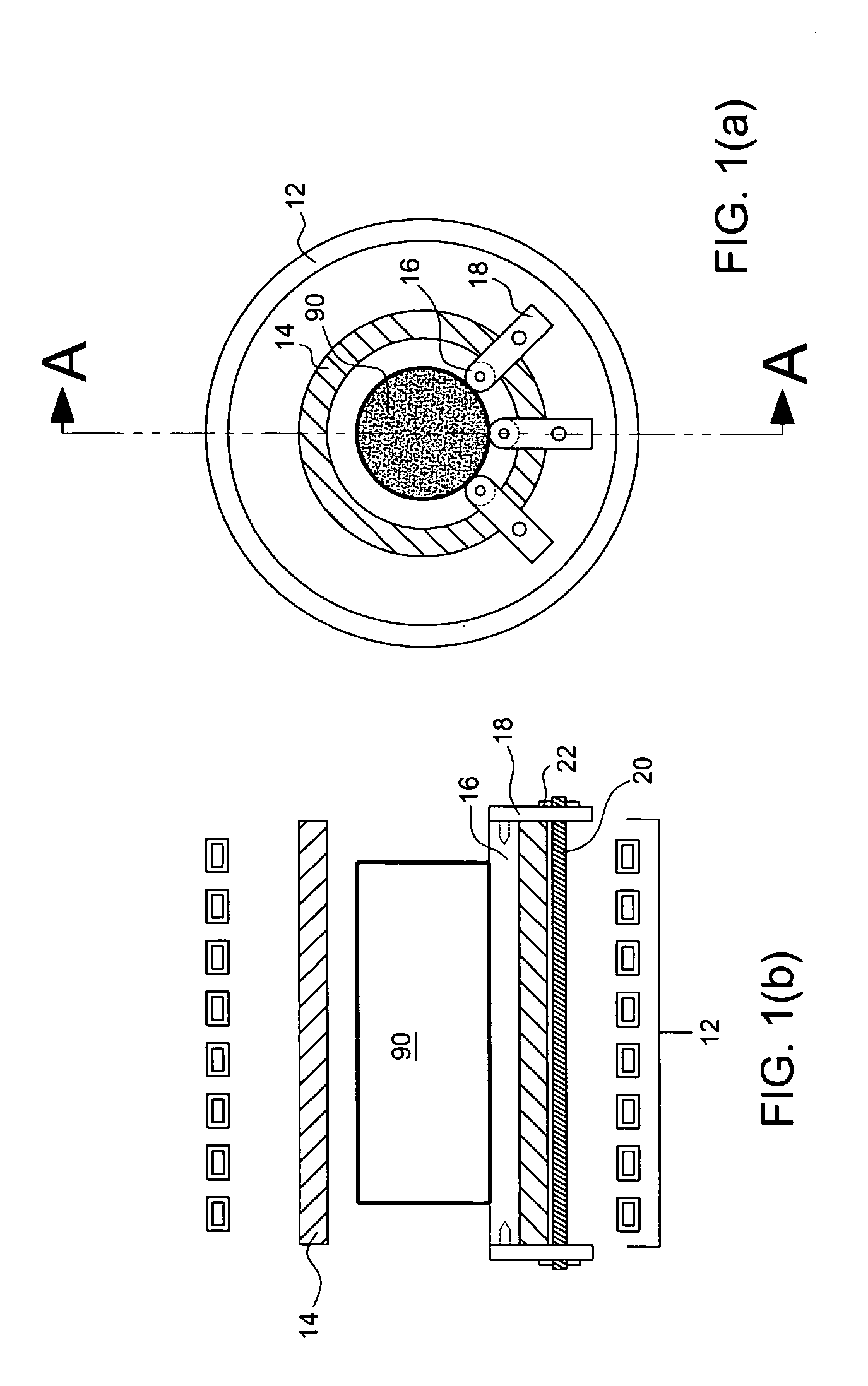
[0016] There is shown in FIG. 1(a) and FIG. 1(b) one example of the billet support system of the present invention. Thermal insulation 14 is generally cylindrical in shape and is inserted within solenoidal induction coil 12. In this non-limiting example of the invention three rails 16 are longitudinally disposed along the interior wall of thermal insulation 14.

[0017] Each rail comprises a heat resistant material, such as a ceramic based on silicon (Si), aluminum (Al), oxygen and nitrogen (generally known as a “sialon” ceramic). See U.S. Pat. No. 4,113,503 for one example of a sialon ceramic. Each rail is generally cylindrical in shape; however the shape of the rail is not limited to cylindrical shapes. In general the rail is shaped to provide a curvilinear seating surface for a billet. A hole is provided at each end of a rail. Each side support member 18 includes an appropriately shaped dowel to fit in the hole. Joining member 20 can be a threaded rod that protrudes at each end thr...


PUM

PropertyMeasurementUnit
magnetic fieldaaaaaaaaaa
heat resistantaaaaaaaaaa
thermal insulationaaaaaaaaaa

Abstract

An apparatus and process are provided for supporting a billet inside an induction coil while the billet is being heated by electric induction. Two or more rails of a heat resistant ceramic material provide a curvilinear surface on which the billet can slide into and out of the coil and sit on during the heating process. Rail position adjustment means may be provided for moving the rails to accommodate billets of various sizes.

Description

CROSS REFERENCE TO RELATED APPLICATIONS [0001] This application claims the benefit of U.S. Provisional Application No. 60 / 538,132 filed Jan. 21, 2004, hereby incorporated herein by reference in its entirety.FIELD OF THE INVENTION [0002] The present invention relates to a billet support system for supporting a billet while it is heated by electric induction. BACKGROUND OF THE INVENTION [0003] A billet composed of an electrically conductive material can be heated by electric induction. The billet is placed inside a solenoidal coil and ac current supplied to the coil establishes a magnetic field that penetrates the billet. The field induces eddy current in the billet that heats the billet. Generally there are three methods of placing a billet inside the coil. In the first method the coil is seated in a container that is placed within the coil. The container may be an open boat-shaped structure formed from a non-magnetic material such as a stainless steel. In the second method the bille...

Claims


Application Information

Patent Timeline
Patent Type & Authority Applications(United States)
IPC IPC(8): H05B6/10B21B45/00
CPCB21B45/004C21D1/42F27D2099/0015F27D99/0006F27B17/00Y02P10/25H05B6/10
Inventor CORDIER, JEAN-PIERRE J.A.DOYON, GARY A.HOOPER, JOHN H.FISHMAN, OLEG S.
Owner INDUCTOTHERM INDS
Why Eureka
Try Eureka