Biological sample observation system and biological sample observation method

a biological sample and observation system technology, applied in the field of biological sample observation system and biological sample observation method, can solve the problems of frequent defocusing, thermal deformation, and frequent defocusing of the focal point, and achieve the effect of reducing the damage to the biological sampl

Inactive Publication Date: 2006-01-05
OLYMPUS CORP
View PDF3 Cites 35 Cited by
  • Summary
  • Abstract
  • Description
  • Claims
  • Application Information

AI Technical Summary

Benefits of technology

[0014] The present invention was achieved in order to solve the above problems, and has an object to provide a biological sample observation system wherein light damage to the biological sample is decreased, and observation can be performed accurately and quickly over a long period of time.

Problems solved by technology

Therefore, due to the temperature drift due to the temperature control for keeping the environment of the culture, the effect of cooling due to flowing of the culture gas, and the heating of a lamp house, and the like, thermal deformation of the mainframe components or the subject of observation readily occurs, and in the technique disclosed in Patent Document 1 and Patent Document 2, there is concern of frequent defocusing where the focal point is displaced with the passage of time.
Therefore, together with the abovementioned reasons, there has been concern of frequent defocusing where the focal position is displaced.
However, if an autofocus operation is performed at each time during the observation, there has been a problem of extending the time for observation due to the autofocus operation.
If the time for observation is extended, for example in a case of observing a large number of cells, the time interval from the observation of the first cell to the observation of the last cell becomes longer, causing a problem in that the results can not be dealt with as observation results for the same time.
However, if as mentioned above the time of observation differs depending on the order of observation, there is a problem in that accurate results can not be obtained, even if sets of information obtained by observation are compared.
If the time for photoirradiation is extended, the concentration of active oxygen in the cells is increased, causing a problem in that the active oxygen damages the cells in the culturing process.

Method used


Image

  • Biological sample observation system and biological sample observation method
  • Biological sample observation system and biological sample observation method
  • Biological sample observation system and biological sample observation method

Examples


first embodiment

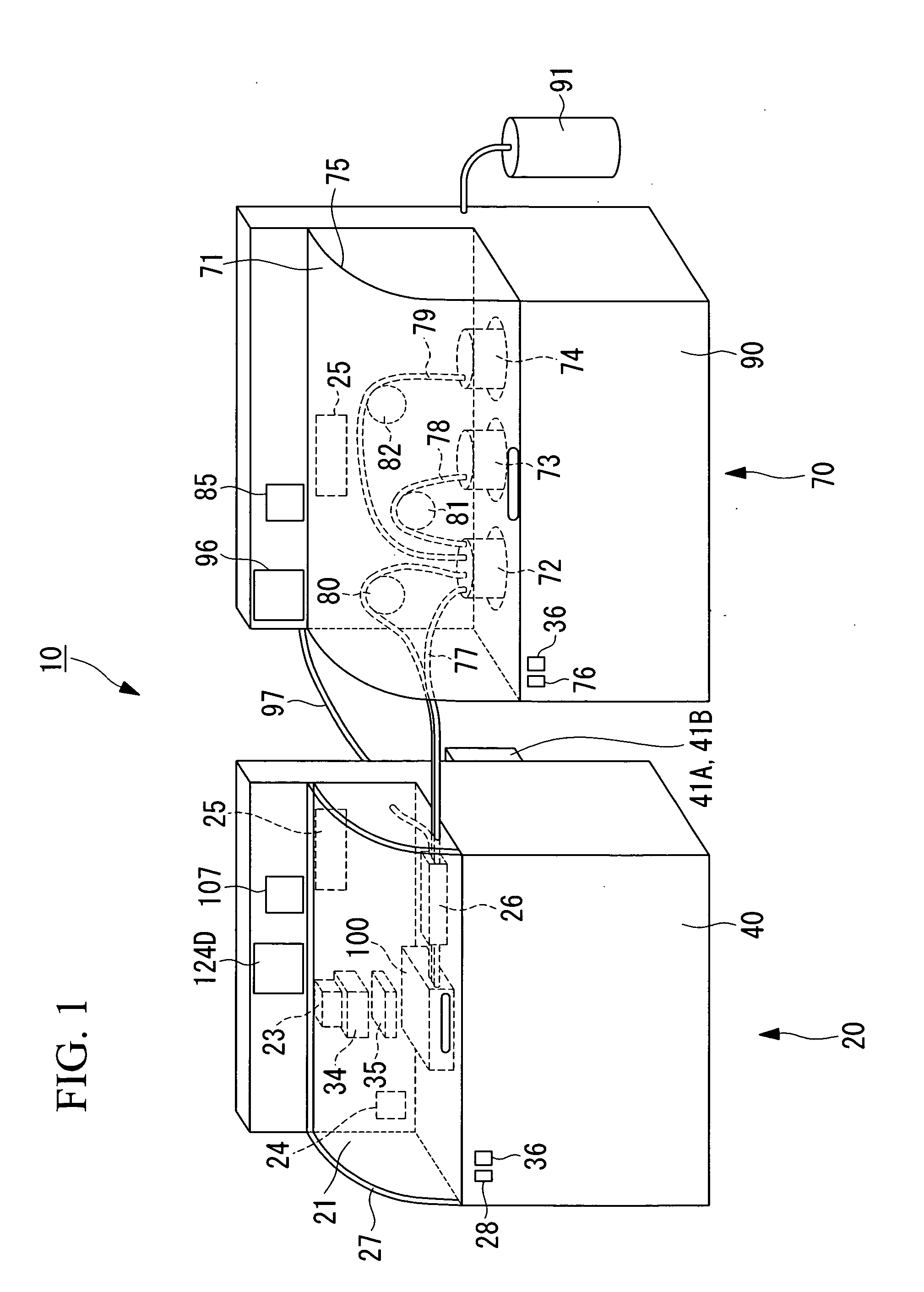
[0042] Hereunder is a description of a biological sample observation system according to a first embodiment of the present invention, with reference to FIG. 1 to FIG. 17.

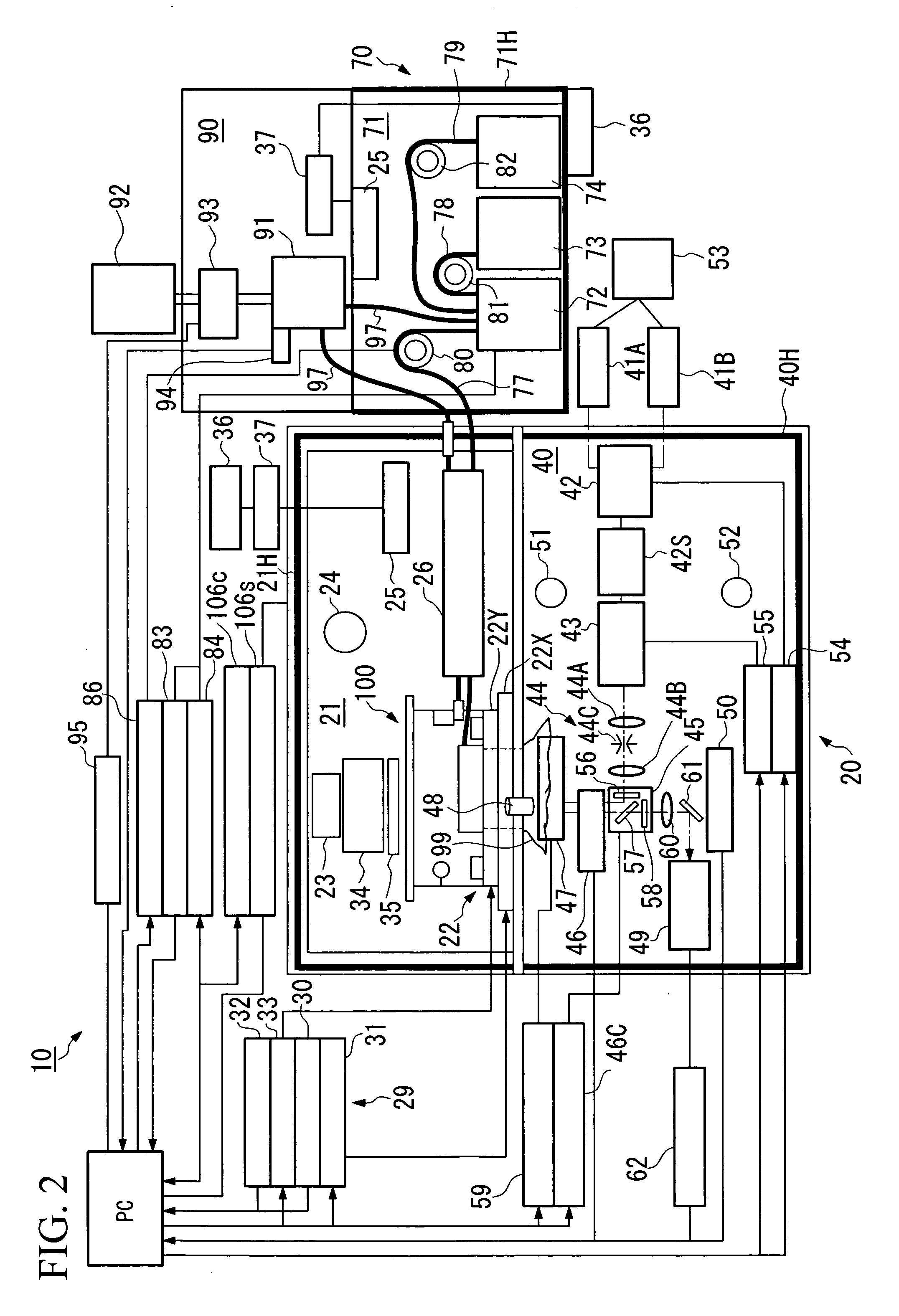
[0043]FIG. 1 is a perspective view showing the outline of the biological sample observation system according to the present embodiment. FIG. 2 is a schematic diagram showing the system structure of the biological sample observation system thereof.

[0044] As shown in FIG. 1 and FIG. 2, a biological sample observation system 10 schematically comprises a detection unit 20, and a culturing unit 70. The detection unit 20 and the culturing unit 70 are desirably arranged close to each other. More preferably, these units 20 and 70 are arranged in contact with each other.

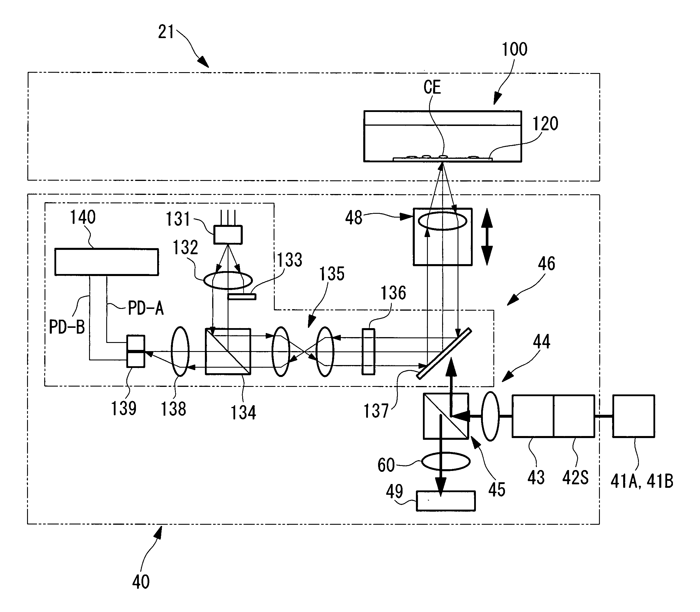
[0045] As shown in FIG. 1 and FIG. 2, the detection unit 20 schematically comprises a heat-insulating box 21 for containing cells (biological sample) CE inside, and a detection section 40 which measures the cells CE.

[0046] The heat insulating box 21 compr...

second embodiment

[0230] Next is a description of a second embodiment of the present invention, with reference to FIG. 18.

[0231] The basic structure of the biological sample observation system of the present embodiment is similar to that of the first embodiment. However, the difference from the first embodiment is the point that a time lapse observation is performed. Therefore, in the present embodiment, the procedure for time lapse observation is described using FIG. 18, and the description of the structure of the biological sample observation system and the like is omitted.

[0232]FIG. 18 is a flowchart showing the flow of the procedure for time lapse observation according to the present embodiment.

[0233] For the same observation procedures as those of the first embodiment, the same reference symbols are used, and the description thereof is omitted.

[0234] Firstly, as shown in FIG. 18, when the observation of the cells CE is started, the X axis operation stage 22X and the Y axis operation stage 22...


PUM


Abstract

An object is to provide a biological sample observation system wherein light damage to the biological sample is decreased, and observation can be performed accurately and quickly over a long period of time. A biological sample observation system which continuously obtains information on a biological sample that is cultured inside of a culturing container has: an imaging section which observes mutually different regions that are previously selected, among regions to be observed including the biological sample, through an object lens for observing the biological sample in the culturing container through a part of the culturing container; an autofocus section which detects the focusing of the object lens with respect to a predetermined region among the regions to be observed; and a focusing drive control section which controls the focusing of the object lens when the biological sample is observed using the imaging section, based on the detection result of the focusing previously performed by the autofocus section. After the focus detection is performed by the autofocus section, without being intervened by the focus detection using the autofocus section, and the different regions are continuously observed by the imaging section, with the focusing controlled by the focusing drive control section.

Description

BACKGROUND OF THE INVENTION [0001] 1. Field of the Invention [0002] The present invention relates to autofocusing on a cultured biological sample, used in a device which detects information caused by the reaction of the biological sample being cultured. [0003] This application is based on Japanese Patent Application No. 2004-180064, the content of which is incorporated herein by reference. [0004] 2. Description of Related Art [0005] Recently, automation of various functions of survey instruments using a microscope is in progress, and an autofocus function for focusing on a specimen has been an essential function for automation. [0006] The microscope autofocus is also employed for a survey instrument for a specimen sealed in a slide glass. For example, there is known an autofocus technique using an infrared reflection film as disclosed in Japanese Unexamined Patent Application, First Publication No. Hei08-82747. Furthermore, there is known a technique wherein a slide glass or a cover...

Claims


Application Information

Patent Timeline
Patent Type & Authority Applications(United States)
IPC IPC(8): G02B27/40
CPCG02B21/365G02B21/241G02B21/245
Inventor IMABAYASHI, HIROYUKIMURAKI, KAYURISUZUKI, YOSHIMASA
Owner OLYMPUS CORP
Why Eureka
Try Eureka