
Image display medium and image writing apparatus

a technology of image display medium and writing apparatus, which is applied in the direction of instruments, computing, electric digital data processing, etc., can solve the problems of increasing the size of the device on the writing side, unable to realize its compactness, and difficulty in bringing all of the pins into contact with the electrode, so as to reduce the number of poor contacts, improve reliability, and minimize the number of terminals for supplying the voltage to the image display medium

Inactive Publication Date: 2006-01-05
FUJIFILM BUSINESS INNOVATION CORP
View PDF7 Cites 9 Cited by
  • Summary
  • Abstract
  • Description
  • Claims
  • Application Information

AI Technical Summary

Benefits of technology

[0010] However, according to a conventional image display medium, where the cost reduction, compactness and flexibility of the image display medium as described in JP-A-2001-301233 is indented, a driving IC will not be loaded on the image display medium, but loaded on the side of the image writing apparatus. In this case, the connection between the image display medium side and the driving IC are implemented by pressure-welding pins on electrodes or by means of the configuration as described in Patent Reference 2. However, in using the pins, it is difficult to bring all of large number of pins into contact with the electrodes. Further, in the configuration described in JP-A-8-201782, the light receiving elements on the display panel are arranged on a line on the electrode terminals. This increases the size of the device on the writing side, and makes it impossible to realize its compactness. Further, in order to carry out the photoelectric conversion on the display panel, a battery is required, thus leading to cost increase.
[0011] Therefore an object of this invention is to provide an image display medium with high reliability capable of realizing cost reduction, compactness and flexibility.
[0014] The above selecting unit can be constructed by a plurality of function elements for applying the above voltage in such a manner that it is operated by the light, heat, magnetic field or pressure received as the driving signal. By receiving the external driving signal without using the contact, the number of poor contacts can be reduced, thereby improving the reliability.
[0015] In accordance with the above image display medium, the number of terminals supplied with the voltage and the driving signal by light, heat, magnetic field or pressure is externally received from e.g. an image writing apparatus so that the number of poor contacts can be reduced, thereby improving the reliability. In addition, the battery is not required and loading of the driving IC is not required. This enables the cost reduction, compactness and flexibility.
[0017] The driving signal generating elements may be those capable of operating the active elements of the image display medium using light, heat, magnetic field or pressure. By transmitting the driving signal to the image display medium without using any contact, the number of poor contacts can be reduced, thereby improving the reliability.
[0018] In accordance with the above image writing apparatus, the number of terminals for supplying the voltage to the image display medium can be minimized, thus realizing the compactness.

Problems solved by technology

However, in using the pins, it is difficult to bring all of large number of pins into contact with the electrodes.
This increases the size of the device on the writing side, and makes it impossible to realize its compactness.
Further, in order to carry out the photoelectric conversion on the display panel, a battery is required, thus leading to cost increase.

Method used


Image

  • Image display medium and image writing apparatus
  • Image display medium and image writing apparatus
  • Image display medium and image writing apparatus

Examples


embodiment 1

(Entire Configuration)

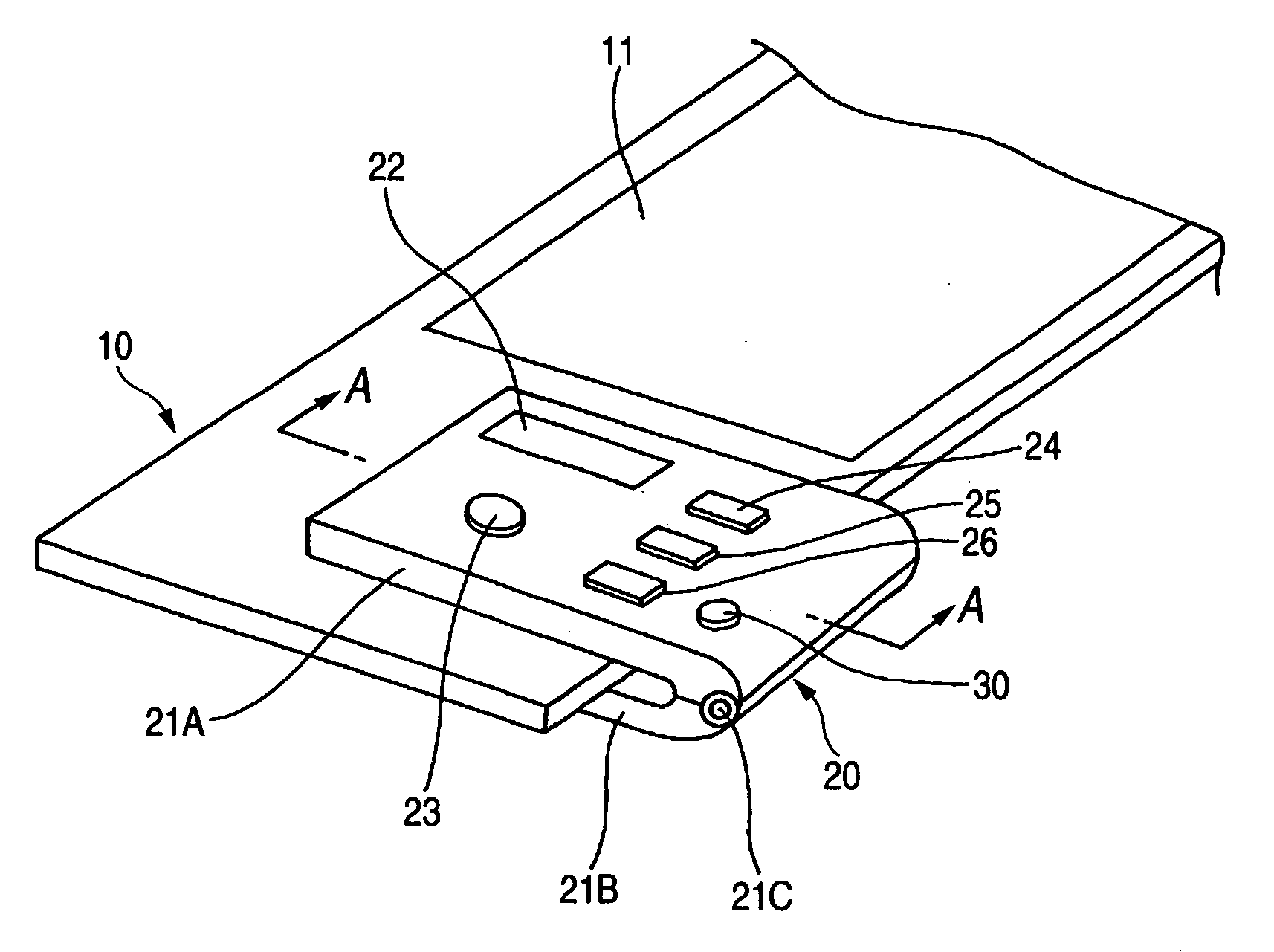
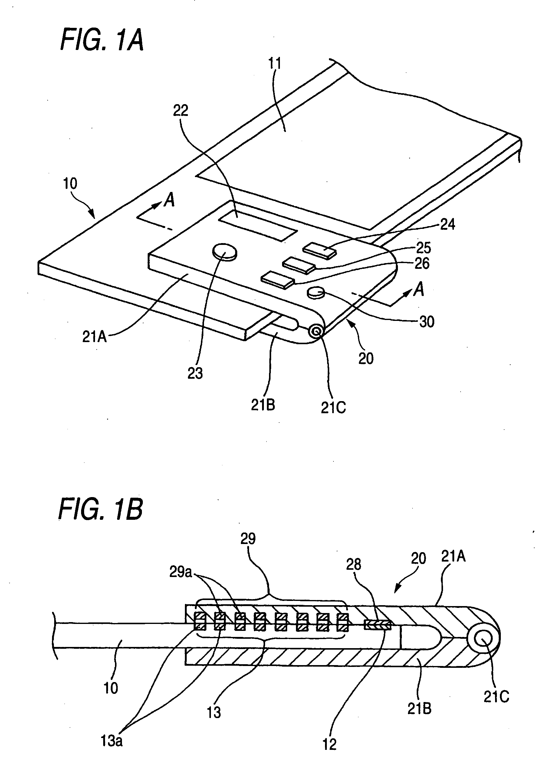
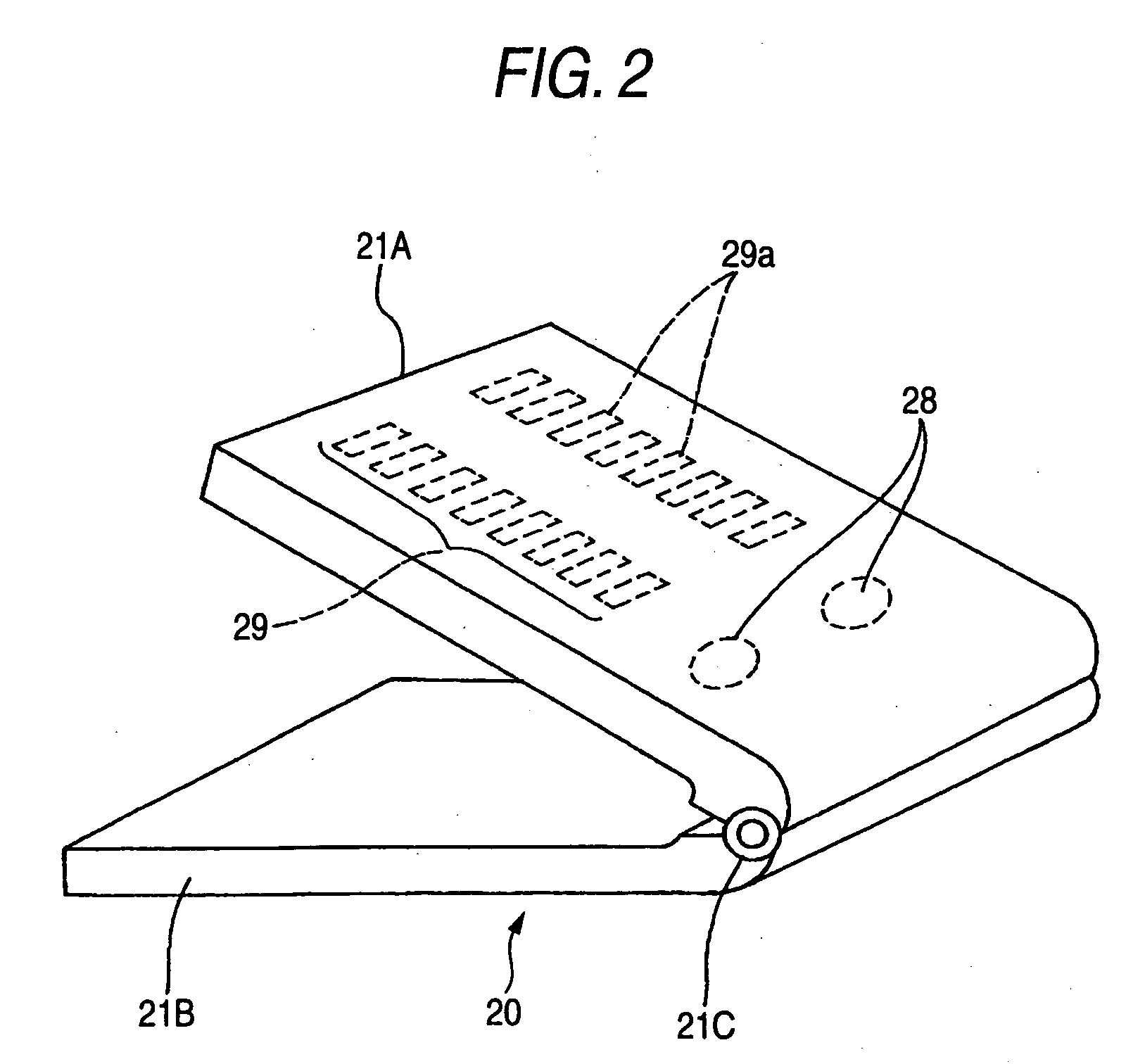
[0044]FIGS. 1A and 1B show an electronic paper and an image writing apparatus according to the first embodiment of this invention; FIG. 1A shows the entire configuration and FIG. 1B shows the section taken in line A-A in FIG. 1A. FIG. 2 is a perspective view of the image writing apparatus in its opened state.

[0045] An electronic paper 10 serving as an image display medium has a thin square shape and is made flexible. The electronic paper 10 is provided with a display unit 11 having a memory characteristic. Further, as seen from FIG. 1B, the electronic paper 1, on its surface, is provided with a pair of power receiving electrodes 12 serving as input terminals and a light receiving array 13 for photoelectric conversion including light receiving elements 13a serving as functional elements whose number corresponds the number (here, 16) of input signals.

[0046] An image writing apparatus 20 for writing an image on the electronic paper 10 is designed to be detacha...

embodiment 2

[0071]FIG. 7 shows the image display medium and image writing apparatus according to the second embodiment. The image writing apparatus 20 according to this embodiment has a structure in which a matrix display unit 31 constructed of a liquid crystal display is provided on the upper body 21A in place of the LED array 29 in the first embodiment, and the electronic paper 10 according to this embodiment has a structure in which a matrix light receiving area 16 including a plurality of light receiving elements 16a arranged in a matrix shape is provided in place of the light receiving element array 13 in the first embodiment. The remaining structure according to this embodiment is the same as that of the first embodiment.

[0072] The matrix display unit 16 consists of 16 light receiving elements 16a of e.g. photo-diodes (PDs) arranged in the matrix shape, and has a size equal to or smaller that the display region of the matrix display unit 31.

[0073] Incidentally, the matrix display unit 3...

embodiment 3

[0079]FIG. 9 shows the electronic paper and image writing apparatus according to the third embodiment of this invention. FIG. 10 shows the electronic paper according to the third embodiment. In FIG. 9, FIG. 9A is a sectional view taken in line A-A in FIG. 1A and FIG. 9B is a perspective view of the image writing apparatus shown in FIG. 9A in its opened state.

[0080] In this embodiment, the electronic paper 10 is constituted so that almost the entire region of its front surface serves as the display unit 11. As shown in FIG. 10, the power receiving electrodes 12 and light receiving element array 13 are arranged on the rear surface of the electronic paper 10.

[0081] In the image writing apparatus 20, as seen from FIG. 9B, the power supplying terminals 28 and LED array 29 are not arranged on the inner face of the upper body 21A but on the inner face of the lower body 21B. The remaining configuration is the same as the first embodiment. The operation of the third embodiment, which is th...


PUM


Abstract

A voltage is supplied from an image writing apparatus to the power receiving electrode of an electronic paper and an optical signal is applied to light receiving elements of the electronic paper from the LEDs of the image writing apparatus. Then, the light receiving elements perform a switching operation to apply the voltage to row electrodes and column electrodes of a display unit including a plurality of pixels, thus making display.

Description

BACKGROUND OF THE INVENTION [0001] 1. Field of the Invention [0002] This invention relates to an image display medium having a memory characteristic and its image writing apparatus, and more particularly to an image display medium with high reliability and capable of realizing cost reduction, compactness and flexibility, and an image writing apparatus capable of realizing compactness. [0003] 2. Description of the Related Art [0004] In recent years, as an image display medium, in addition to a paper medium and an electronic display device, the image display medium called electronic paper or digital paper having both advantages of the electronic display device and paper has been widely noticed. [0005] This image display medium, which has the memory characteristic for display, has only to be supplied with energy for write by a driving device or an external information writing device only when information is rewritten, and is not required to be supplied with energy for maintaining the d...

Claims


Application Information

Patent Timeline
IPC IPC(8): G09G3/34
CPCG06F3/147G09G2380/02G09G2330/02G09G2310/0221
Inventor SAITO, YASUNORIMITA, TSUNEMASAYAMAMOTO, YASUOMORIYAMA, HIROAKIKOSHIMIZU, MINORUKAKINUMA, TAKEOISHII, TSUTOMUTAKEUCHI, TAKAYUKISASAKI, SHIGEHIKO
Owner FUJIFILM BUSINESS INNOVATION CORP
Learn More