Automatic identification symbology suitable for contact lens manufacturing verification

a technology of automatic identification and symbology, applied in the field of identifying characteristics of ophthalmic lenses, can solve the problems of increasing tool costs, cluttered peripheral zone of lenses, and many markings on lenses, and achieve the effect of minimizing the amount of markings

Inactive Publication Date: 2006-01-05
BAUSCH & LOMB INC
View PDF16 Cites 24 Cited by
  • Summary
  • Abstract
  • Description
  • Claims
  • Application Information

AI Technical Summary

Benefits of technology

[0007] The present invention provides a method for marking ophthalmic lenses such as intraocular or contact lenses with identifying indicia that indicates any desired parameter of the lens while minimizing the amount of markings needing to be placed on the lens.

Problems solved by technology

One drawback of these prior art methods is that a lens may have many markings that clutter the peripheral zone of the lens.
Furthermore, markings which form depressions in the mold tool (which are ultimately transferred to the lens during the molding of the lens) are difficult to clean which is can lead to increased tool costs.

Method used


Image

  • Automatic identification symbology suitable for contact lens manufacturing verification
  • Automatic identification symbology suitable for contact lens manufacturing verification

Examples


Embodiment Construction

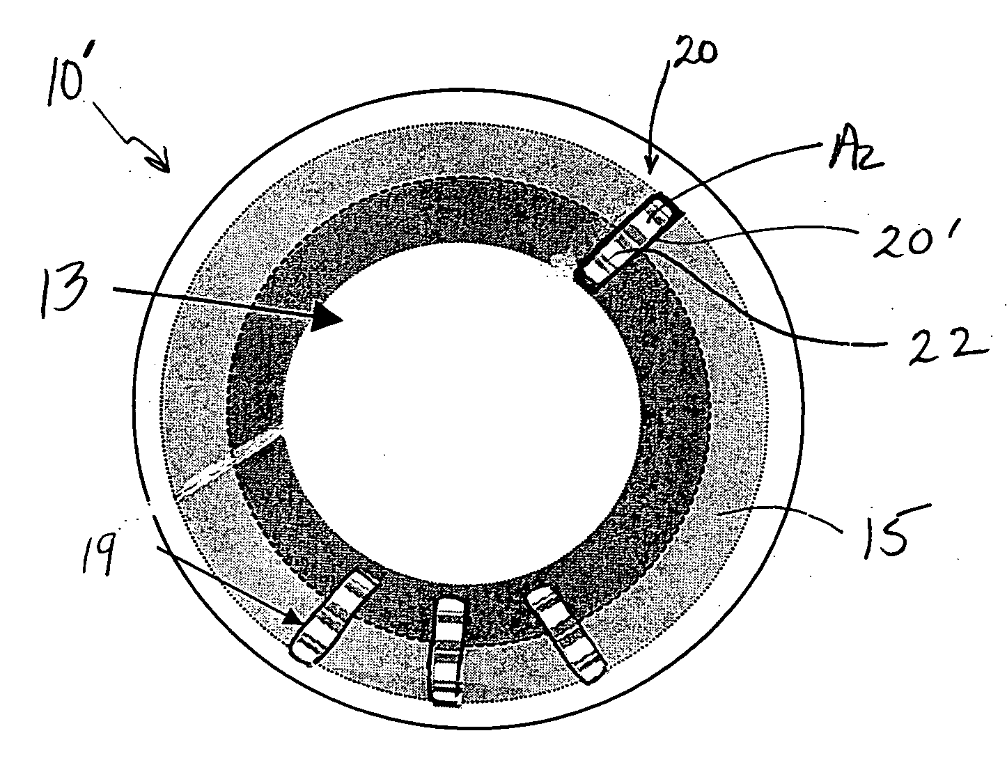
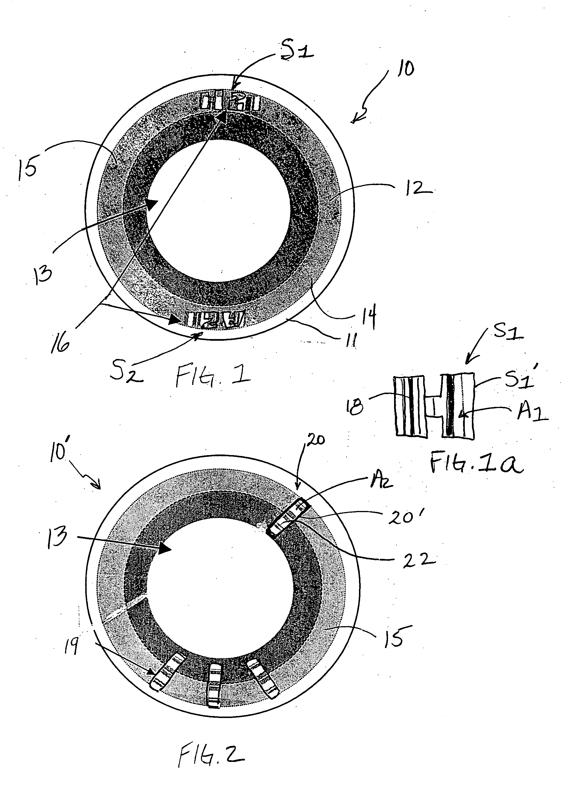
[0013] Referring now to the drawing, there is seen in FIG. 1 an exemplary contact lens 10 having an anterior surface 12 and opposing posterior surface 14 surrounded by a peripheral edge 11. At the center of the lens is optical zone 13 surrounded by peripheral zone 15. Lens 10 includes a marking 16 which may consist of one or symbols S1 and S2 located. This marking may indicate any desired property of the lens, e.g., the power of the lens, the manufacturer, an inversion indicator (to tell the wearer which surface goes against the eye), etc.

[0014] In the embodiment of FIG. 1, symbols S1 and S2 may be formed on the anterior and posterior tools that make the opposite surfaces of the contact lens as disclosed in the '826 patent to reduce the number of unique tools required to mold a series of lenses. As disclosed in the '826 patent, the symbol may comprise an alphanumeric code, for example. As seen in FIG. 1a, the letter “H” in symbol S1 has a perimeter S1′ and defining an internal area...


PUM


Abstract

A method of identifying one or more characteristics of an ophthalmic lens by embedding a second marking inside the perimeter of a first marking formed on the lens. In one embodiment, the first marking may be a toric marking indicative of the ballast and / or cylindrical axis and the second marking, placed inside the first marking, may indicate one or more other lens characteristic such as power, SKU or lot number, for example. The invention includes a lens made according to the method.

Description

BACKGROUND OF THE INVENTION [0001] The present invention relates to a method for identifying characteristics of an ophthalmic lens such as an intraocular lens or contact lens, and lenses made according to the method. [0002] One type of contact lens is commonly referred to as a “spherical contact lens”, i.e., contact lenses designed to provide a spherical optical correction (or “power”) to compensate for myopia (nearsightedness) or hypermetropia (farsightedness). Such contact lenses are also designed with fitting parameters, especially lens diameter and effective base curve. Accordingly, a prescription for spherical contact lenses will typically specify a spherical correction (power), lens diameter and base curve. Using hydrogel lenses as an example, manufacturers typically market a series of spherical hydrogel contact lenses, each series including lenses having common fitting parameters and offering powers in 0.25 or 0.50 diopter increments. [0003] In addition to spherical lenses, t...

Claims


Application Information

Patent Timeline
Patent Type & Authority Applications(United States)
IPC IPC(8): G02C7/04B24B13/005G02C7/02
CPCG02C7/021
Inventor DUGGAN, ROBERTFRUMUSA, GERALD J.
Owner BAUSCH & LOMB INC
Why Eureka
Try Eureka