Slip ring unit with a printed circuit board

a technology of printed circuit board and ring unit, which is applied in the direction of current collectors, electrical devices, rotary current collectors, etc., can solve the problems of stator supply and torque required for relative movement between the rotors, and achieve the effect of simple and cost-effective construction

Inactive Publication Date: 2006-01-05
ANGERPOINTNER LUDWIG
View PDF24 Cites 36 Cited by
  • Summary
  • Abstract
  • Description
  • Claims
  • Application Information

AI Technical Summary

Benefits of technology

[0012] An object of the present invention is therefore based on making possible a slip ring unit

Problems solved by technology

The above-described known devices have the disadvantage that the torque required for the relative movement between the rotor and the

Method used


Image

  • Slip ring unit with a printed circuit board
  • Slip ring unit with a printed circuit board
  • Slip ring unit with a printed circuit board

Examples


Embodiment Construction

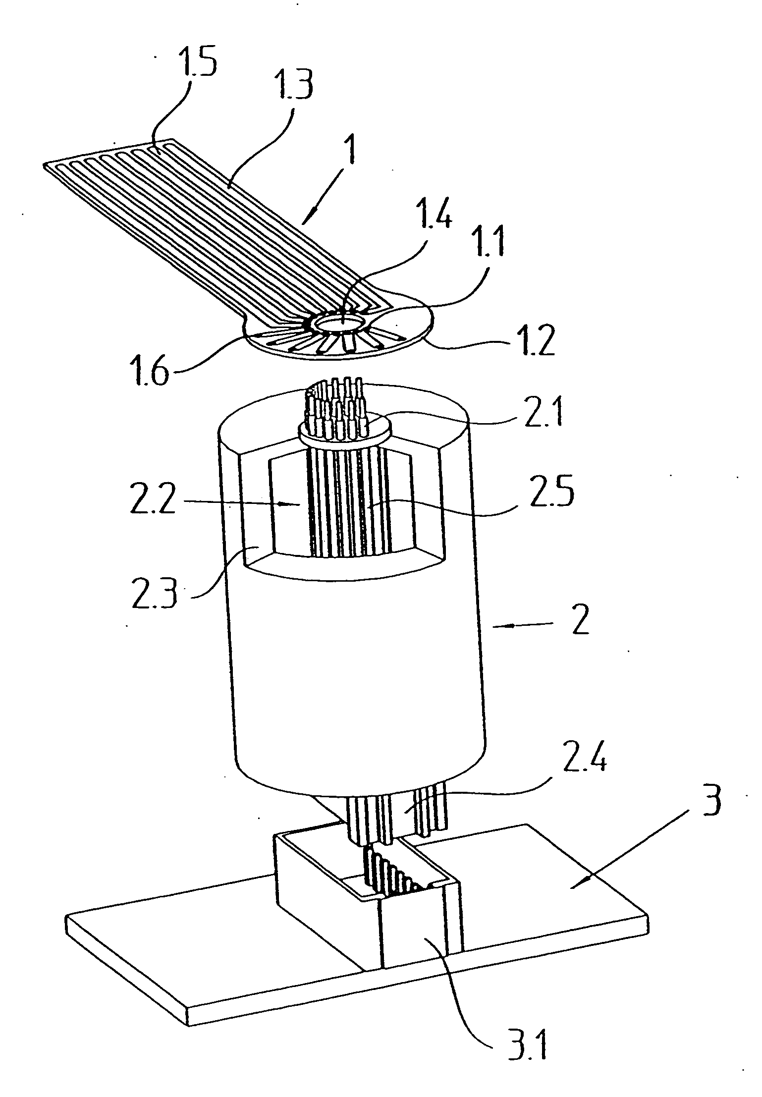
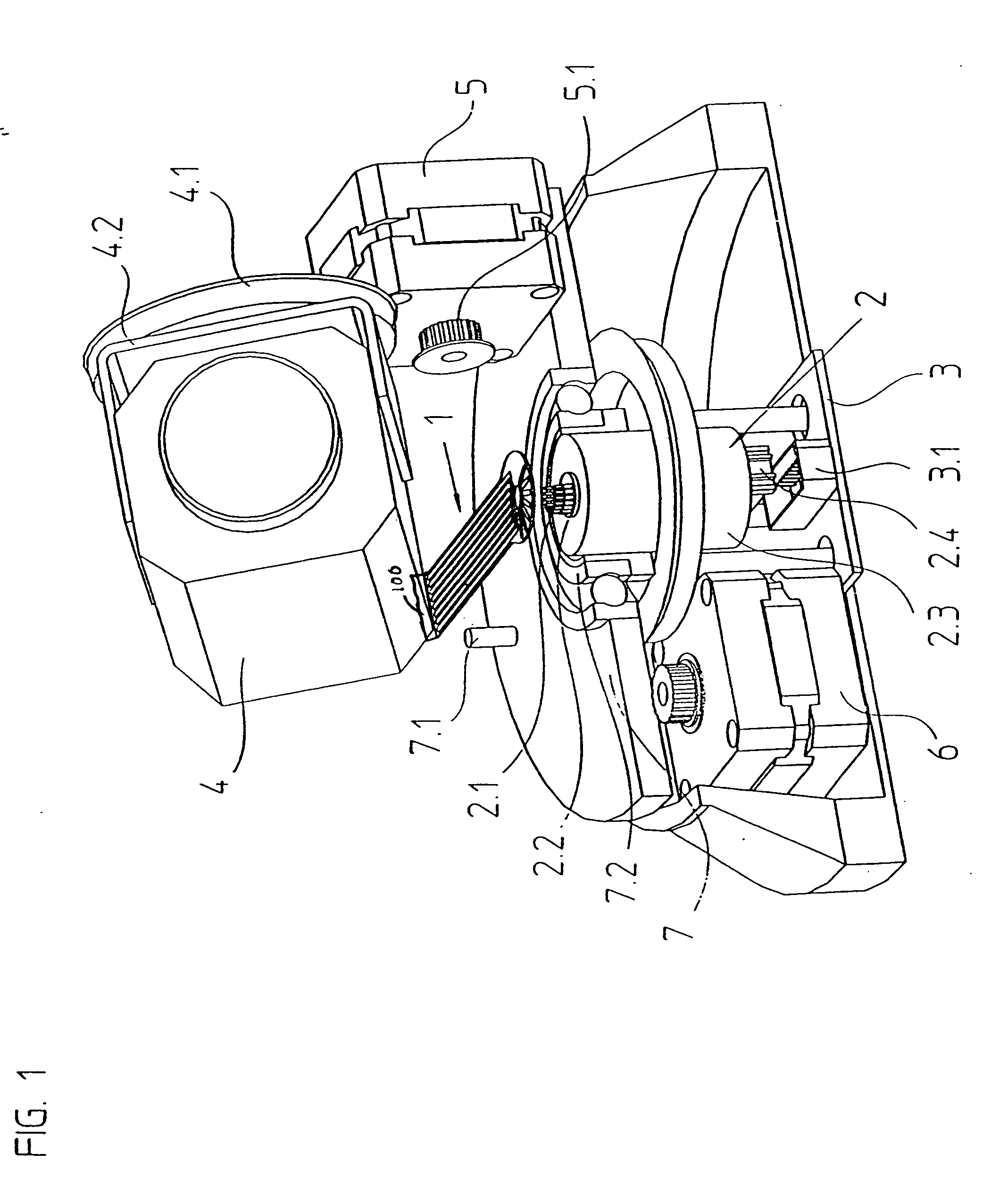
[0027] An exploded representation is shown in FIG. 1, which makes clear the application of the device in accordance with the present invention for the operation of a remote-controlled camera 4. The representation of the cable connection was omitted in this drawing figure for reasons of clarity. Also, not shown in this drawing figure is the remote operation, or the remote control of the tilt drive 5 and the pivot drive 6, as well as the camera 4.

[0028] Essentially, two electronic function groups are housed on a stationary board 3, which are required for the correct operation of a remote-controlled camera 4 (the function groups are not shown in detail in the drawing figures). The first function group includes electronic components intended for controlling the tilt drive 5 and the zoom regulation of the camera 4. The other function group receives the electronic signals containing the optical information from the camera 4, and processes them into a conventional video signal format.

[00...


PUM


Abstract

A device for transferring electric currents that includes a slip ring unit that has a rotor with connecting wires and a stator and a printed circuit board fastened to the rotor, wherein the printed circuit board includes connectors in electrical contact with the connecting wires, wherein a torque required for rotary movement between the rotor and the stator is introduced via the printed circuit board.

Description

[0001] Applicant claims, under 35 U.S.C. § 119, the benefit of priority of the filing date of Mar. 15, 2001 of a German patent application, copy attached, Serial Number 101 12 895.9, filed on the aforementioned date, the entire contents of which is incorporated herein by reference. BACKGROUND OF THE INVENTION [0002] 1. Field of the Invention [0003] The present invention relates to a device for transmitting electrical currents, including a slip ring unit and a printed circuit board, as well as to its employment in connection with remote-controlled objects. [0004] 2. Discussion of Related Art [0005] Slip rings are employed in many technical fields for transmitting electrical signals or electrical power from a stationary electrical unit to a rotating electrical unit. [0006] For example, slip rings are employed for the operation of remote-controlled cameras. In this application, electrical signals must be transmitted from the pivotable camera to an electronic evaluating device, and furt...

Claims


Application Information

Patent Timeline
IPC IPC(8): H01R39/00H01R39/08H01R39/34H01R39/64
CPCH01R39/08H01R39/34H01R12/7076H01R43/10H01R39/64
Inventor ANGERPOINTNER, LUDWIG
Owner ANGERPOINTNER LUDWIG
Why Eureka
Try Eureka