Motion measurement method, motion measurement system, and motion measurement program

a technology of motion measurement and motion measurement system, applied in the field of motion measurement method, motion measurement system, and motion measurement program, can solve the problems of muscle not being able to make the given motion with the weak muscle, he is very likely to have an uncomfortable feeling, and achieve the effect of accurately measuring the variabl

Inactive Publication Date: 2006-01-05
HONDA MOTOR CO LTD
View PDF0 Cites 42 Cited by
  • Summary
  • Abstract
  • Description
  • Claims
  • Application Information

AI Technical Summary

Benefits of technology

[0028] According to this aspect of the present invention, the computer can be provided with a function of accurately measuring the variabl

Problems solved by technology

On the other hand, a man using a walking aid device due to his weak muscle cannot make the given motion wit

Method used


Image

  • Motion measurement method, motion measurement system, and motion measurement program
  • Motion measurement method, motion measurement system, and motion measurement program
  • Motion measurement method, motion measurement system, and motion measurement program

Examples


first embodiment

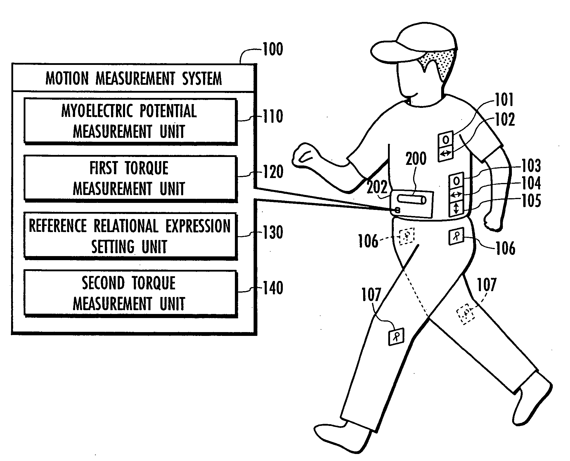
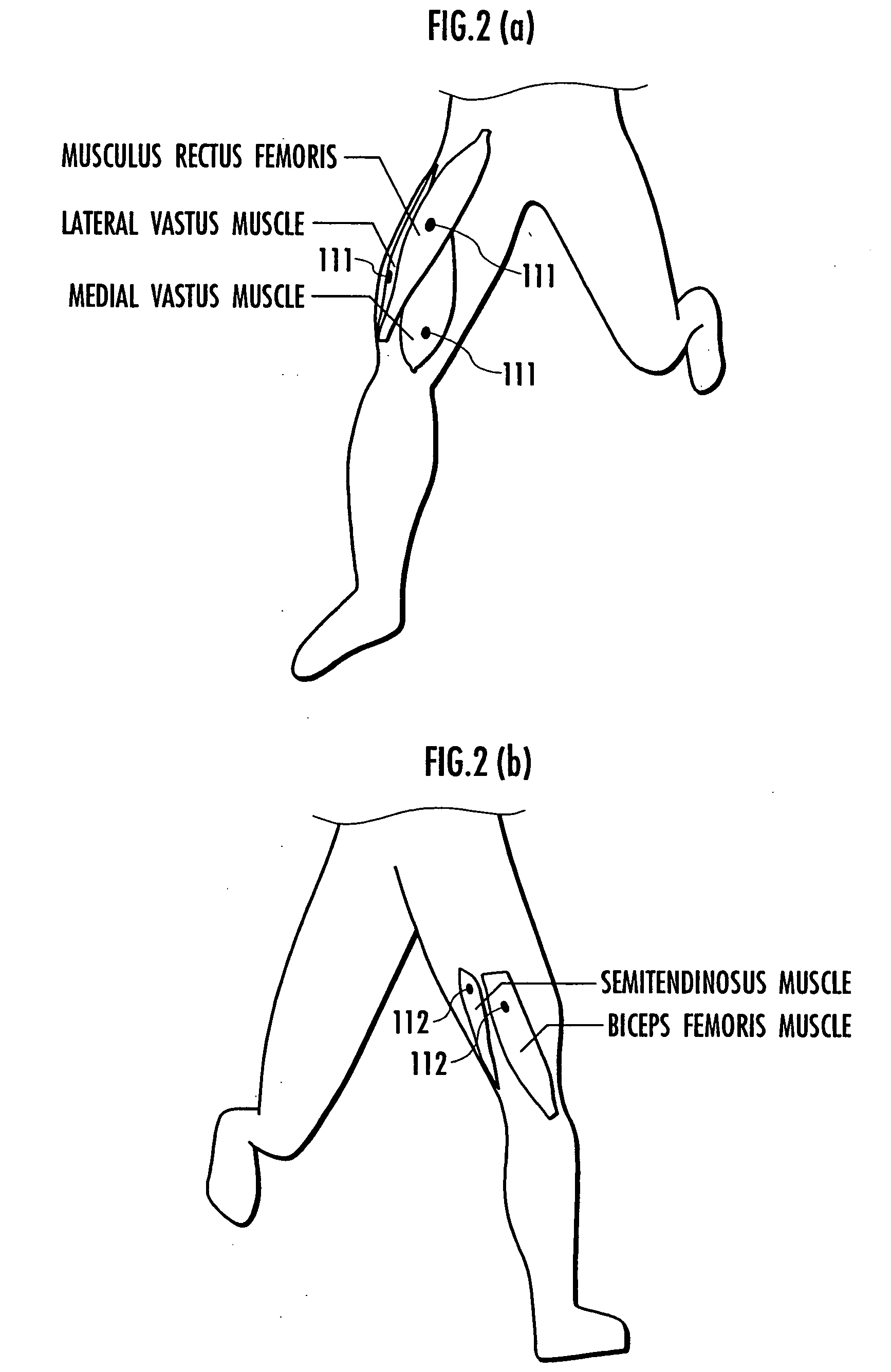
[0039] First, the motion measurement system according to the present invention will be described by using FIGS. 1 to 5.

[0040] A motion measurement system 100 shown in FIG. 1 is for use in measuring motions of a human being (an animal). The motion measurement system 100 comprises a chest gyro sensor 101 for outputting a signal according to a tilt angular velocity of a human chest whose motions are to be measured, a chest fore-and-aft acceleration sensor 102 for outputting a signal corresponding to a fore-and-aft acceleration of the chest, a lumbar gyro sensor 103 for outputting a signal corresponding to a tilt angular velocity of a lumbar, a lumbar fore-and-aft acceleration sensor 104 for outputting a signal corresponding to a fore-and-aft acceleration of the lumbar, a lumbar vertical acceleration sensor 105 for outputting a signal corresponding to a vertical acceleration of the lumbar, a hip joint angle sensor 106 for outputting a signal corresponding to a flexion angle of a hip joi...

second embodiment

[0063] The following describes a motion measurement system according to the present invention with reference to FIG. 6 and FIG. 7.

[0064] A configuration of the motion measurement system of the second embodiment of the present invention will now be described with reference to FIG. 6. A motion measurement system 100 of the second embodiment shown in FIG. 6 does not include the chest gyro sensor 101, the chest fore-and-aft acceleration sensor 102, the lumbar gyro sensor 103, the lumbar fore-and-aft acceleration sensor 104, and the lumbar vertical acceleration sensor 105. On the other hand, it is the same in the configuration as the motion measurement system of the first embodiment shown in FIG. 1 and FIG. 2 except that it additionally includes a motion condition determination unit 150. Therefore, the same reference numerals are retained for the same parts and their description is omitted here.

[0065] The motion condition determination unit 150 determines a human motion condition on the...


PUM


Abstract

A method, system, and program enabling a variable varying with animal's motions such as a joint torque to be accurately measured in a series of the animal's motions. First, a reference relational expression representing a relation between myoelectric potentials and a knee joint torque is set on the basis of the myoelectric potentials and the knee joint torque (variable) measured by using an inverse dynamics model. Then, the knee joint torque is measured on the basis of the measured myoelectric potentials and according to the reference relational expression. For example, if an animal makes first and second motions continuously, first a reference relational expression is set on the basis of myoelectric potentials measured in the first motion and a knee joint torque corresponding to the first motion. Then, a knee joint torque corresponding to the second motion is measured on the basis of the myoelectric potentials measured in the second motion and according to the reference relational expression. The first and second motions are arbitrary and the animal is not forced to make a given motion.

Description

BACKGROUND OF THE INVENTION [0001] 1. Field of the Invention [0002] The present invention relates to a method of measuring animal's motions made by activities of muscle fibers, a system for measuring the animal's motions, and a program enabling a computer to have functions for measuring the animal's motions. [0003] 2. Related Background Art [0004] There has been suggested a technology of measuring myoelectric signals generated in muscles of an animal including a human being and measuring a torque or the like of a joint of the animal based on the myoelectric signals (refer to, for example, Japanese Laid-Open Patent Publication (Kokai) No. 2001-286451). According to the related art, the myoelectric signals are measured, first, with given forces produced in a motion region of a subject, the plurality of myoelectric signals measured are translated to a plurality of pseudo tensile forces, and then the maximum value among the plurality of pseudo tensile forces is determined as a normalize...

Claims


Application Information

Patent Timeline
IPC IPC(8): A61B5/04A61B5/103
CPCA61B5/0488A61B5/4528A61B5/103A61B5/389
Inventor ENDO, YOSUKEHARA, RITSUO
Owner HONDA MOTOR CO LTD
Why Eureka
Try Eureka