Lockout connector arrangement for implantable medical device

a technology of lockout connector and implantable medical device, which is applied in the field of implantable electrical medical device lockout connector arrangement, can solve the problems that the df-1 defibrillation lead cannot be inadvertently electrically connected, and the non-cardiac stimulation lead pin cannot make effective electrical connection with the is-1 pacemaker lead port, so as to achieve effective lockout operation and effectively bar potential harm

Inactive Publication Date: 2006-01-05
CVRX
View PDF14 Cites 54 Cited by
  • Summary
  • Abstract
  • Description
  • Claims
  • Application Information

AI Technical Summary

Benefits of technology

[0013] The present invention is a lockout connector arrangement for implantable medical devices having at least one port for receiving a non-cardiac lead connector that selectively permits only certain electrical leads to be connected to the implantable medical device. Specifically, a lead connector pin of a non-cardiac lead connector is specially designed to be larger than the lead connector pin of a DF-1 defibrillation lead connector port, but smaller than the lead connector pin of an IS-1 pacemaker lead connector port. A corresponding header is provided for an implantable pulse generator in which a connector port for a non-cardiac lead has a proximal-most portion that is larger than the lead connector pin of a DF-1 defibrillation lead, but smaller than the lead connector pin of an IS-1 pacemaker lead. While providing for effective lockout operation, the overall dimensions of the remainder of the lead connector of a preferred embodiment of the present invention remain generally consistent with the IS-1 standards to permit the non-cardiac connector port and connectors to be manufactured with minimal changes to existing header and lead designs.
[0014] A

Problems solved by technology

Conversely, a DF-1 defibrillation lead cannot be inadvertently electrically connected to a non-cardiac port on the implantable pulse g

Method used


Image

  • Lockout connector arrangement for implantable medical device
  • Lockout connector arrangement for implantable medical device
  • Lockout connector arrangement for implantable medical device

Examples


Embodiment Construction

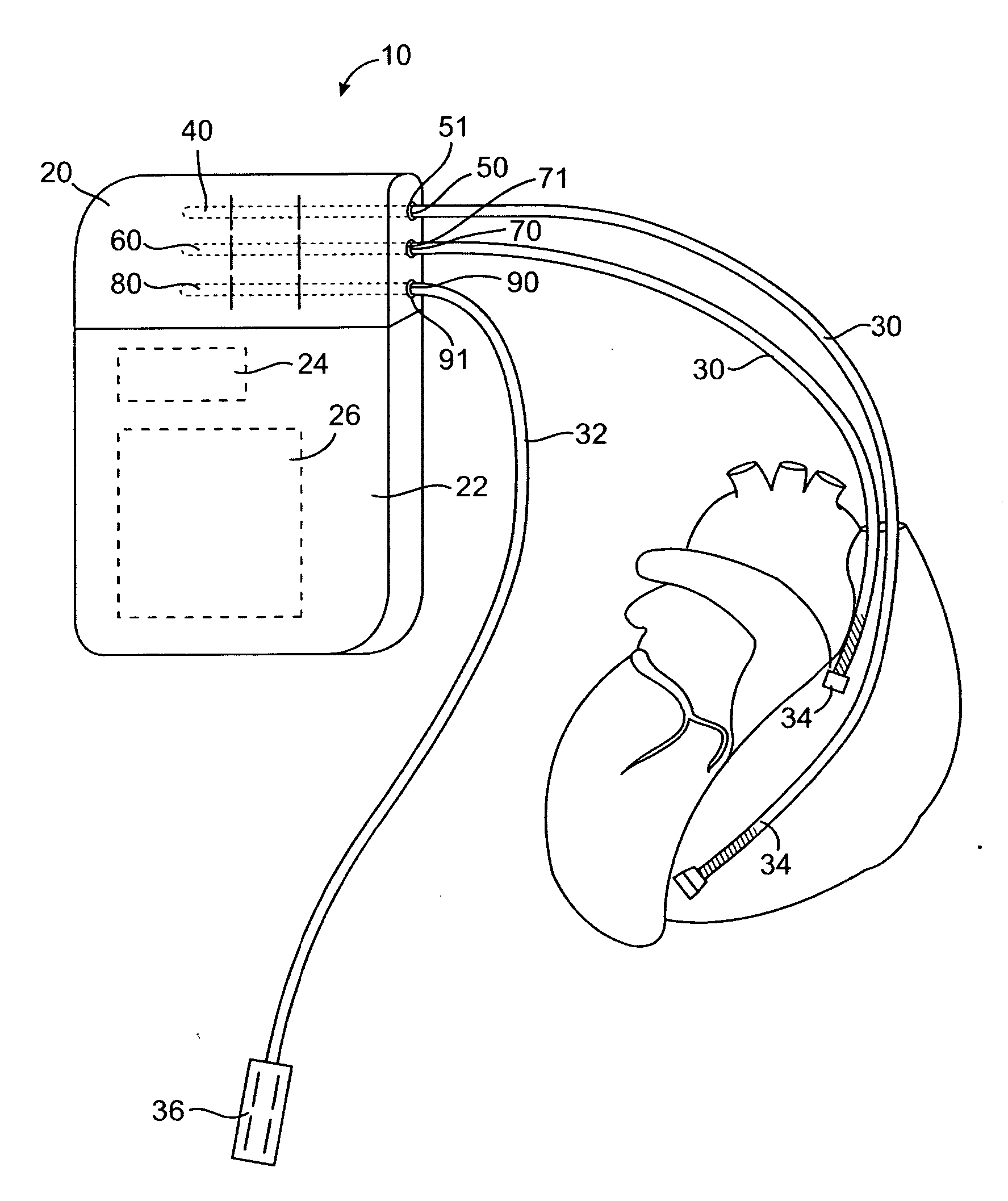
[0022] An implantable pulse generator device typically includes an electrical medical device such as a pacemaker, cardioverter, defibrillator, baroreflex activation device, nerve stimulator, muscle stimulator, implantable monitor or other medical device and one or more electrical leads. Typically, the pulse generator device comprises a case and a header attached to the case. The case typically contains the electronics and the power source (usually a battery) for the implantable pulse generator. The leads are connected to the implantable pulse generator through ports in the header.

[0023] Referring to FIG. 1, there is shown an implantable pulse generator device 10 that is comprised of a header 20 and a case 22 containing a power source 24 and electronics 26. The header portion 20 of the implantable pulse generator device 10 is typically formed of a molded thermoplastic material, such as an acrylic material, and includes a plurality of ports 50 (pacing), 70 (defibrillation), and 90 (n...


PUM


Abstract

A lockout connector arrangement for implantable medical devices having at least one port for receiving a non-cardiac lead connector selectively permits only certain electrical leads to be connected to the implantable medical device. A lead connector pin of a non-cardiac lead connector is specially designed to be larger than a DF-1 lead connector pin, but smaller than an IS-1 lead connector pin. A corresponding header of implantable pulse generator has a connector port for a non-cardiac lead with a proximal-most portion that is larger than the DF-1 lead connector pin, but smaller than the IS-1 lead connector pin; and otherwise generally consistent with the other dimensions of an ISO standard IS-1 pacemaker lead connector.

Description

CROSS-REFERENCES TO RELATED APPLICATIONS [0001] The present application is a non-provisional of U.S. Patent Application Ser. No. 60 / 584,647 (Attorney Docket No. 021433-001400US), filed Jun. 30, 2005, the full disclosure of which is incorporated herein by reference.BACKGROUND OF THE INVENTION [0002] 1. Field of the Invention [0003] This invention relates to implantable electrical medical devices used to stimulate the heart, other tissue, and nerves, to control the functioning of the particular organ or bodily function. More particularly, the present invention is directed to electrical lead connector arrangements for implantable medical devices that selectively permit only certain electrical leads to be connected to the implantable medical device. [0004] 2. Background of the Invention [0005] Implantable pulse generator medical devices are well known in the art, and include medical devices such as pacemakers, defibrillators, baroreflex activation devices and muscle and nerve stimulator...

Claims


Application Information

Patent Timeline
IPC IPC(8): A61N1/375
CPCA61N1/3752
Inventor ROSSING, MARTIN A.BOLEA, STEPHEN L.HJELLE, AARONHENRY, JAMES T.PEDERSEN, BRAD D.
Owner CVRX
Why Eureka
Try Eureka