Method of managing a multi-bit-cell flash memory

a multi-bit, flash memory technology, applied in the field of flash memory, can solve the problems of lower reliability of mbc than sbc, lower quality specification of mbc cells in terms of data retention time, and lower performan

Active Publication Date: 2006-01-05
WESTERN DIGITAL ISRAEL LTD
View PDF14 Cites 155 Cited by
  • Summary
  • Abstract
  • Description
  • Claims
  • Application Information

AI Technical Summary

Benefits of technology

[0035] More generally, the scope of the present invention extends beyond flash memories to include any of the memories discussed in the Chen patent cited above: memories that include non-volatile arrays of storage elements such that each storage element has a storage window divisible into a plurality of defined ranges of storage levels that represent one or more bits of data. The cells of a MBC flash memory are examples of such storage elements. The blocks of a MBC flash memory are examples of such non-volatile arrays.
[0036] In the context of the present invention, “programming” or “setting” a flag cell or a non-volatile storage element to represent one member of a set of integers means placing the flag cell or the nonvolatile storage element in a state that corresponds only to that integer and to no other integer of the set. For example, one way to program a flag cell to represent a selected one of the integers 1, 2 and 3 is to program the cell with N=3 to be in the second threshold voltage range from the left in FIG. 4 below (between a threshold voltage of zero and a threshold voltage of V1) to represent the integer 1, to be in the fourth threshold voltage range from the left in FIG. 4 below (between a threshold voltage of V2 and a threshold voltage of V3) to represent the integer 2, and to be in the rightmost threshold voltage range in FIG. 4 below to represent the integer 3._Preferably, if two or more flag cells are used to represent the same integer for a set of other cells, all of the flag cells are programmed identically.

Problems solved by technology

However, there are also some drawbacks to using MBC flash—the average read and write times of MBC memories are longer than of SLC memories, resulting in lower performance.
Also, the reliability of MBC is lower than SBC.
Thus, a disturbance in the threshold voltage (e.g. leaking of the stored charge causing a threshold voltage drift, interference from operations on neighboring cells, etc.) that may have gone unnoticed in SBC because of the large gap between the two states, might cause an MBC cell to move from one state to another, resulting in an erroneous bit.
The end result is a lower quality specification of MBC cells in terms of data retention time or the endurance of the device to many write / erase cycles.
However, such dynamic mode switching of flash blocks during run-time creates a problem.
Such reading under the wrong mode produces unpredictable results.
If such mistakes are allowed to take place, the contents of the storage device will become useless.
But such a solution has very undesirable consequences.
First, each “useful” write operation must now be accompanied by an “auxiliary” write for updating the table, resulting in lower write performance.
Second, the complexity of the flash management software is significantly increased—protection must be provided against loss of the table due to a block becoming bad; protection must be provided against a power loss occurring in the middle of updating the table, etc.

Method used


Image

  • Method of managing a multi-bit-cell flash memory
  • Method of managing a multi-bit-cell flash memory
  • Method of managing a multi-bit-cell flash memory

Examples


second embodiment

[0058] The above embodiment of the present invention has been described in terms of distinguishing between two different values of N. A similar second embodiment of the present invention can be used to distinguish among more than two possible values of N.

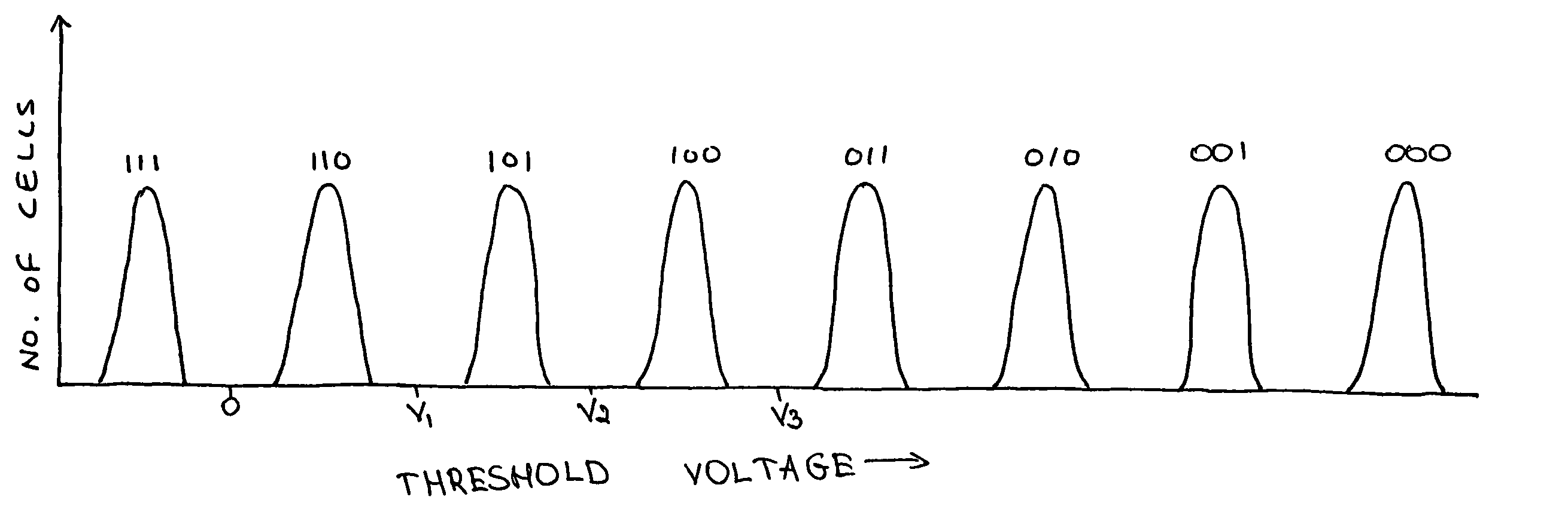
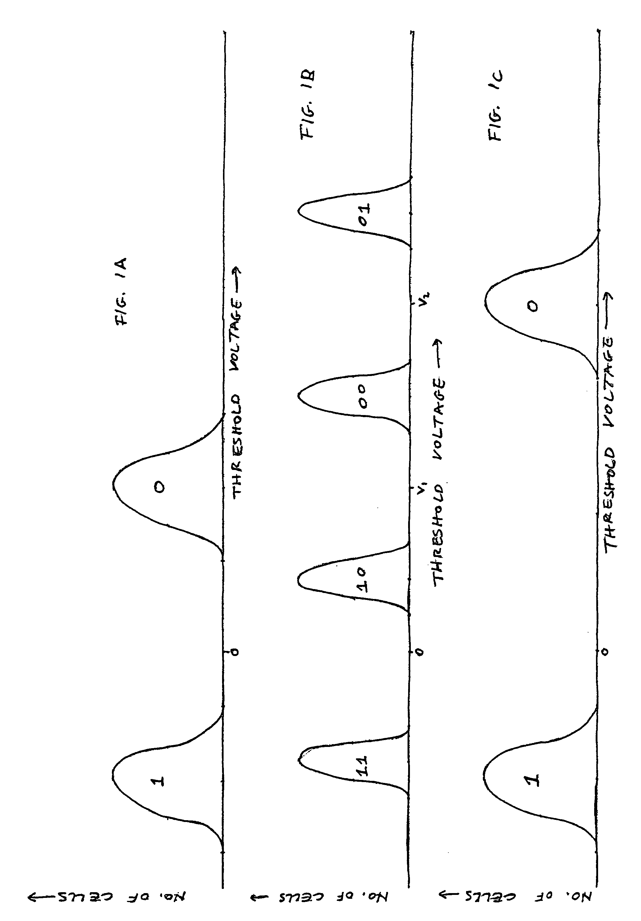
[0059] Let us assume (as an example) that N is selectable from a group containing exactly three values. This is for example the case when a block of cells can be programmed in one of three modes such as: [0060] a. Each cell storing one bit. [0061] b. Each cell storing two bits. [0062] c. Each cell storing three bits.

first embodiment

[0063] One way of implementing the methods of the present invention for distinguishing between the possible modes is to assign two cells (“C1” and “C2”) per block as flag cells, use only one bit of each flag cell, and define a correspondence between the values of those bits and the possible modes. For example: [0064] i. One bit per cell indicated by cell C1=left unprogrammed, cell C2=left unprogrammed. [0065] ii. Two bits per cell indicated by cell C1=left unprogrammed, cell C2=programmed. [0066] iii. Three bits per cell indicated by cell C1=programmed, cell C2 programmed.

[0067] When attempting to find out the mode with which the block was programmed, we read the flag cells according to the methods of the first embodiment (for example by reading according to the 1-bit programming mode), and then translate the reading from the flag cells into the corresponding mode.

[0068] Although this works, it requires the allocation of at least two cells from each block to act as flag cells. Typ...


PUM


Abstract

A flash memory is managed by reserving one or more cells as flag cells to represent the number N of bits to store in the cells of a memory block, selecting the value of N from at least three candidates, and programming the flag cell(s) to represent the selected value. A flash memory is managed by selecting a value of the number N>2 of bits to store in the cells of a portion (e.g. a block or page) of the memory, reserving one other cell of the memory as a flag cell to represent how many bits actually are stored in each cell of the portion, and, as the cells of the portion are successively programmed with 1≦n≦N bits, programming the flag cell to represent n.

Description

[0001] This patent application claims the benefit of U.S. Provisional Patent Application No. 60 / 624,675, filed Nov. 4, 2004. [0002] This is a continuation-in-part of U.S. patent application Ser. No. 10 / 829,979, filed Apr. 23, 2004FIELD AND BACKGROUND OF THE INVENTION [0003] The present invention relates to flash memories and, more particularly, to a method of managing a flash memory, whose cells can be programmed with either one bit each or more than one bit each, so that the number of bits per cell can be determined upon power-up or during recovery from power loss. [0004] Flash memory devices have been known for many years. Typically, each cell within a flash memory stores one bit of information. Traditionally, the way to store a bit has been by supporting two states of the cell—one state represents a logical “0” and the other state represents a logical “1”. In a flash memory cell the two states are implemented by having a floating gate above the cell's channel (the area connecting...

Claims


Application Information

Patent Timeline
Patent Type & Authority Applications(United States)
IPC IPC(8): G06F12/00
CPCG11C11/5621G11C11/5628G11C2211/5646G11C16/10G11C2211/5641G11C16/0483
Inventor LASSER, MENAHEM
Owner WESTERN DIGITAL ISRAEL LTD
Why Eureka
Try Eureka