Network analyzer, network analyzing method, automatic corrector, correcting method, program, and recording medium

a network analyzer and network analysis technology, applied in error detection/correction, resistance/reactance/impedence, instruments, etc., can solve the problems of inability to obtain erb>1/b> and erb>2/b>, and achieve the effect of correcting measurement system errors

Inactive Publication Date: 2006-01-05
ADVANTEST CORP
View PDF8 Cites 25 Cited by
  • Summary
  • Abstract
  • Description
  • Claims
  • Application Information

AI Technical Summary

Benefits of technology

[0014] The received signal measuring element measures the predetermined parameter (S parameter for example) concerning the received signal, which makes it possible to acquire the measurement system error factor of the receiving element.
[0015] In the case where the frequency of an input signal of a device under test is different from that of the output signal thereof, the measurement system error factor of the receiving element cannot be ignored. Therefore, it is possible to correct measurement system errors by acquiring the measurement system error factor of the receiving element.

Problems solved by technology

These measurement system errors are, for example, an error due to the directionality of bridges as Ed, an error due to frequency tracking as Er, and an error due to source matching as Es.
In such a case, it is impossible to correct errors in such a calibration as above.
Therefore, it is impossible to obtain Er1 and Er2.

Method used


Image

  • Network analyzer, network analyzing method, automatic corrector, correcting method, program, and recording medium
  • Network analyzer, network analyzing method, automatic corrector, correcting method, program, and recording medium
  • Network analyzer, network analyzing method, automatic corrector, correcting method, program, and recording medium

Examples


first embodiment

(a) First Embodiment

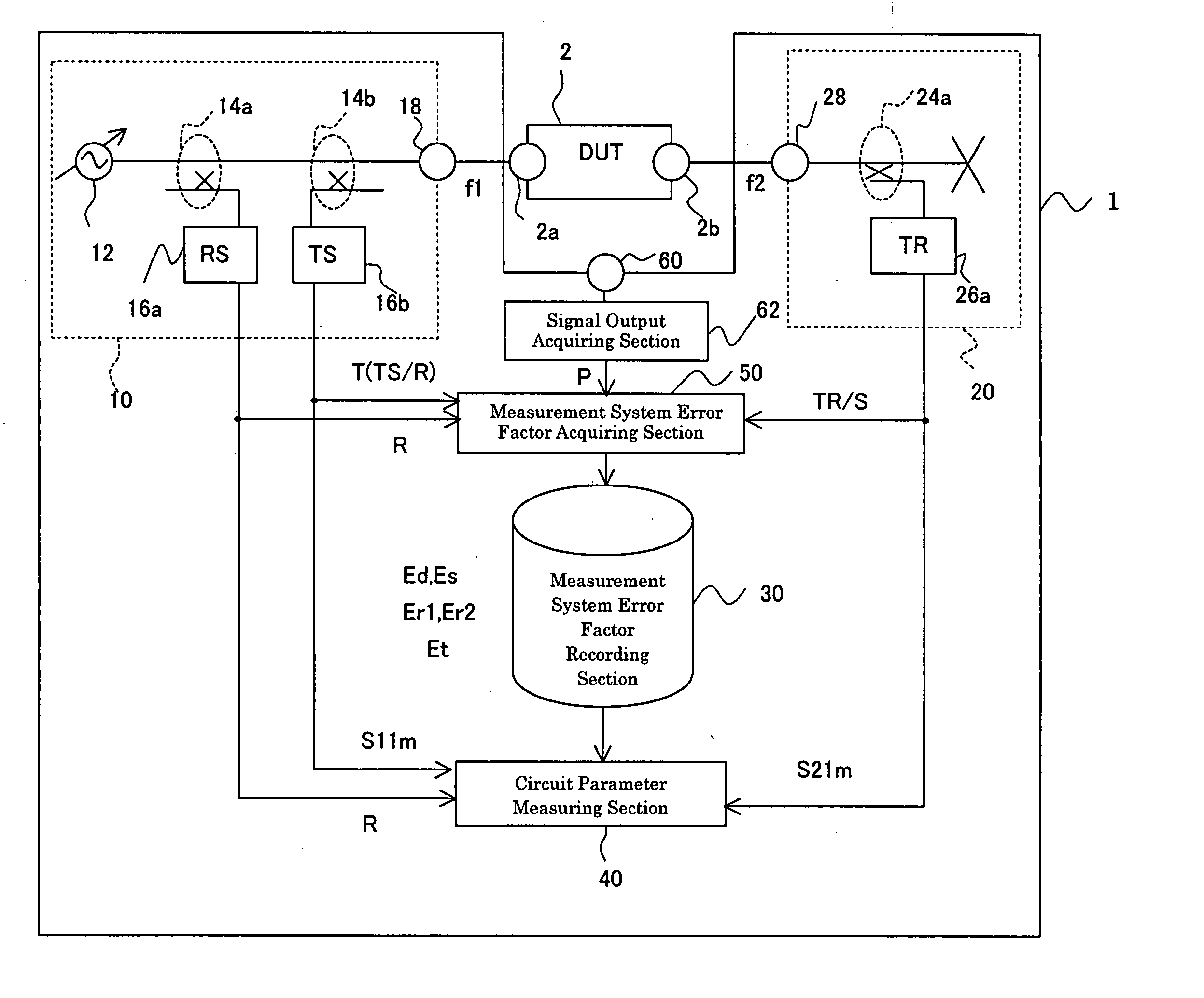
[0093]FIG. 1 is a block diagram showing the configuration of a network analyzer 1 according to the first embodiment. A DUT (Device Under Test) 2 is connected to the network analyzer 1. The network analyzer 1 measures circuit parameters, e.g. S parameters, of the DUT 2. The DUT 2 has an input terminal 2a and an output terminal 2b. There may be a difference between the signal frequency f1 at the input terminal 2a and the signal frequency f2 at the output terminal 2b. For example, if the DUT 2 is a one having frequency conversion functions (mixer for example), f1≠f2 becomes true.

[0094] The network analyzer 1 comprises a signal source 10, a receiving element 20, a measurement system error factor recording section 30, a circuit parameter measuring section 40, a measurement system error factor acquiring section 50, a terminal 60 for power meter, and a signal output acquiring section 62.

[0095] The signal source 10 provides signal to the DUT 2. The signal source 10 has...

second embodiment

(b) Second Embodiment

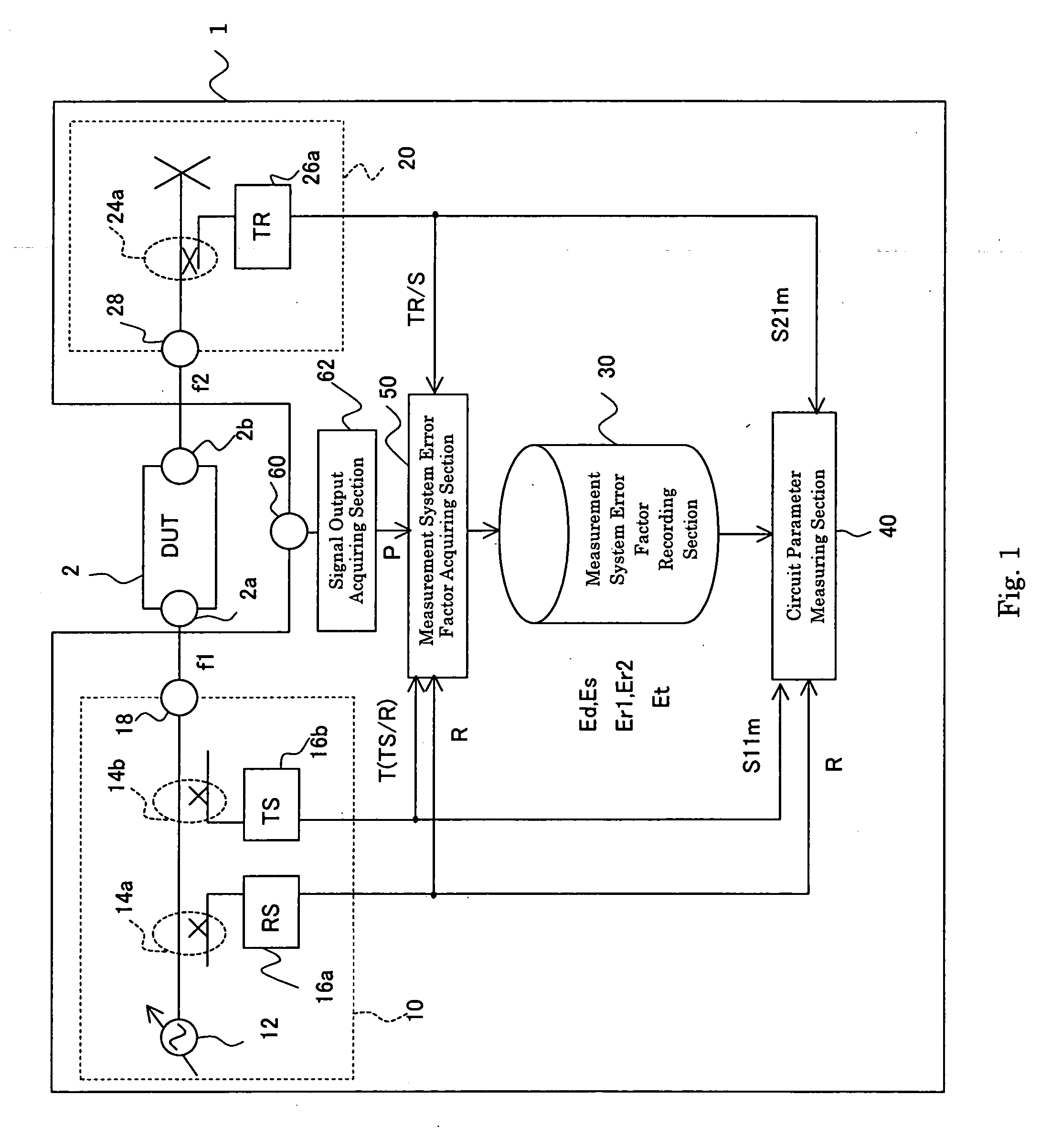
[0136] The second embodiment differs from the first embodiment in that the true S parameters of the DUT 2 (without any effect of the measurement system error factors) S12a and S22a, which are ignored in the first embodiment, are also made measurable.

[0137]FIG. 12 is a block diagram showing the configuration of a network analyzer 1 according to the second embodiment. The network analyzer 1 comprises a signal source 10, a receiving element 20, a measurement system error factor recording section 30, a circuit parameter measuring section 40, a measurement system error factor acquiring section 50, a terminal 60 for power meter, a signal output acquiring section 62, and further a receiving side measurement system error factor recording section 70. Hereinafter, the same numerals are assigned to the same components in the first embodiment above to omit descriptions thereof.

[0138] The signal source 10 has a signal outputting section 12, a switch 13, bridges 14a and 14b...


PUM


Abstract

The error of a measurement system can be corrected even if the frequency of an input signal of a device under test is different from that of the output signal. A signal output acquiring section acquires the power of the input signal by means of a power meter not shown in the drawing. Thus, errors due to frequency tracking can be separated depending on the direction in a signal flow graph. Since a receiver measures the parameter concerning the received signal when a signal source is directly connected to receiving means, the measurement system error factor of the receiving means can be acquired. The parameter of a device under test can be measured while the error is corrected when the results of measurement, concerning the device under test of receivers are combined.

Description

TECHNICAL FIELD [0001] The present invention relates to a network analyzer adapted to calculate and measure circuit parameters of a device under test. BACKGROUND ART [0002] It has conventionally been implemented to measure circuit parameters (S parameters for example) of device under test (DUT). A method for measuring circuit parameters of a device under test (DUT) according to prior art will hereinafter be described with reference to FIG. 20. [0003] A signal with a frequency of f1 is transmitted from a signal source 110 through a DUT 200 to a receiving section 120. This signal is received by the receiving section 120. It is assumed that the frequency of the signal received by the receiving section 120 is f2. The S parameters and frequency characteristics of the DUT 200 can be acquired by measuring the signal received by the receiving section 120. [0004] In the case above, there occur measurement system errors in the measurement caused by, for example, a mismatch between measurement...

Claims


Application Information

Patent Timeline
Patent Type & Authority Applications(United States)
IPC IPC(8): G06F11/00G01R27/28
CPCG01R27/28
Inventor NAKAYAMA, YOSHIKAZUHARUTA, MASATO
Owner ADVANTEST CORP
Why Eureka
Try Eureka