
Method and system for simulating a modular test system

a modular test and test system technology, applied in power supply testing, error detection/correction, instruments, etc., can solve the problems of low or no capability of existing semiconductor testers to simulate test programs, debug test programs, and major cost of semiconductor production, so as to reduce the use of expensive tester equipment.

Inactive Publication Date: 2007-04-24
ADVANTEST AMERICA R & D CENT
View PDF19 Cites 33 Cited by
  • Summary
  • Abstract
  • Description
  • Claims
  • Application Information

AI Technical Summary

Benefits of technology

[0006]The disclosed method for simulating a modular test system provides a simulation framework that can be configured by an end-user. The framework is used to construct a simulation environment to load vendor emulation modules and DUT models, and to execute test programs through the simulation framework API. This method enables new vendor modules to be added to an existing installation, by installing the vendor's software emulation and editing a system configuration file. This method also enables engineers to develop test programs on their own workstations with minimized usage of the expensive tester equipment.

Problems solved by technology

A major cost in semiconductor production is the development and maintenance of test programs that test integrated circuits for viability and functionality.
This activity usually entails many hours of work on the actual tester hardware.
However, existing semiconductor testers have little or no capability for simulating test programs, except for checking the semantics of the test programming language.
This limitation forces engineers to debug their test programs on the actual tester hardware.
But using tester hardware for test program development is not a cost-effective use of the expensive test equipment.
Besides, since a tester is usually shared among groups of engineers, the amount of time allocated to use the tester is limited, which creates a bottleneck in the development of test programs, resulting in a process where development occurs serially.
Such limitations in test program development may delay production of the integrated circuits, which could delay product release and lost market opportunities.

Method used


Image

  • Method and system for simulating a modular test system
  • Method and system for simulating a modular test system
  • Method and system for simulating a modular test system

Examples


Embodiment Construction

[0018]Methods and systems are provided for simulating a modular test system. The following descriptions are presented to enable any person skilled in the art to make and use the invention. Descriptions of specific embodiments and applications are provided only as examples. Various modifications and combinations of the examples described herein will be readily apparent to those skilled in the art, and the general principles defined herein may be applied to other examples and applications without departing from the spirit and scope of the invention. Thus, the present invention is not intended to be limited to the examples described and shown, but is to be accorded the widest scope consistent with the principles and features disclosed herein.

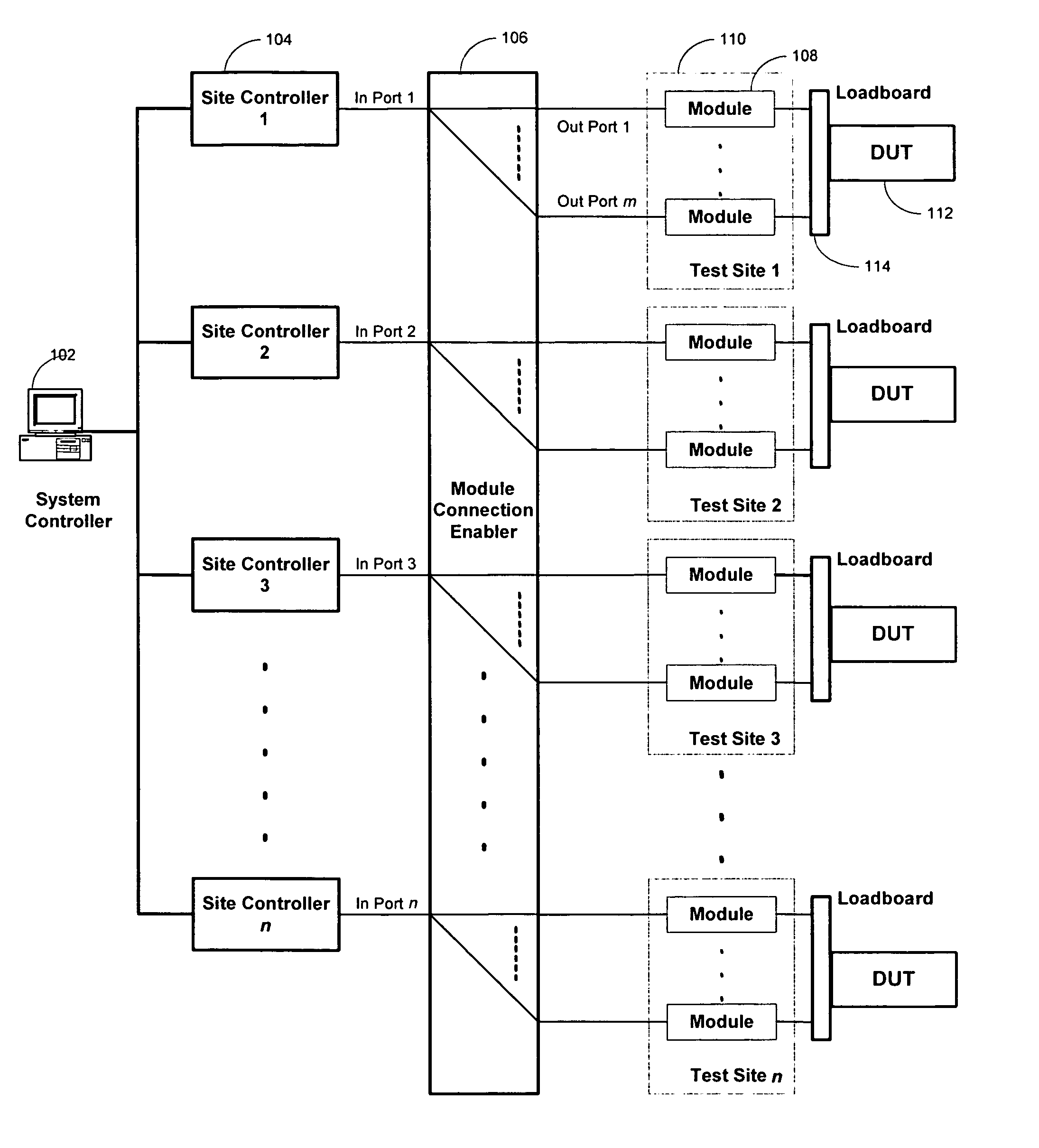
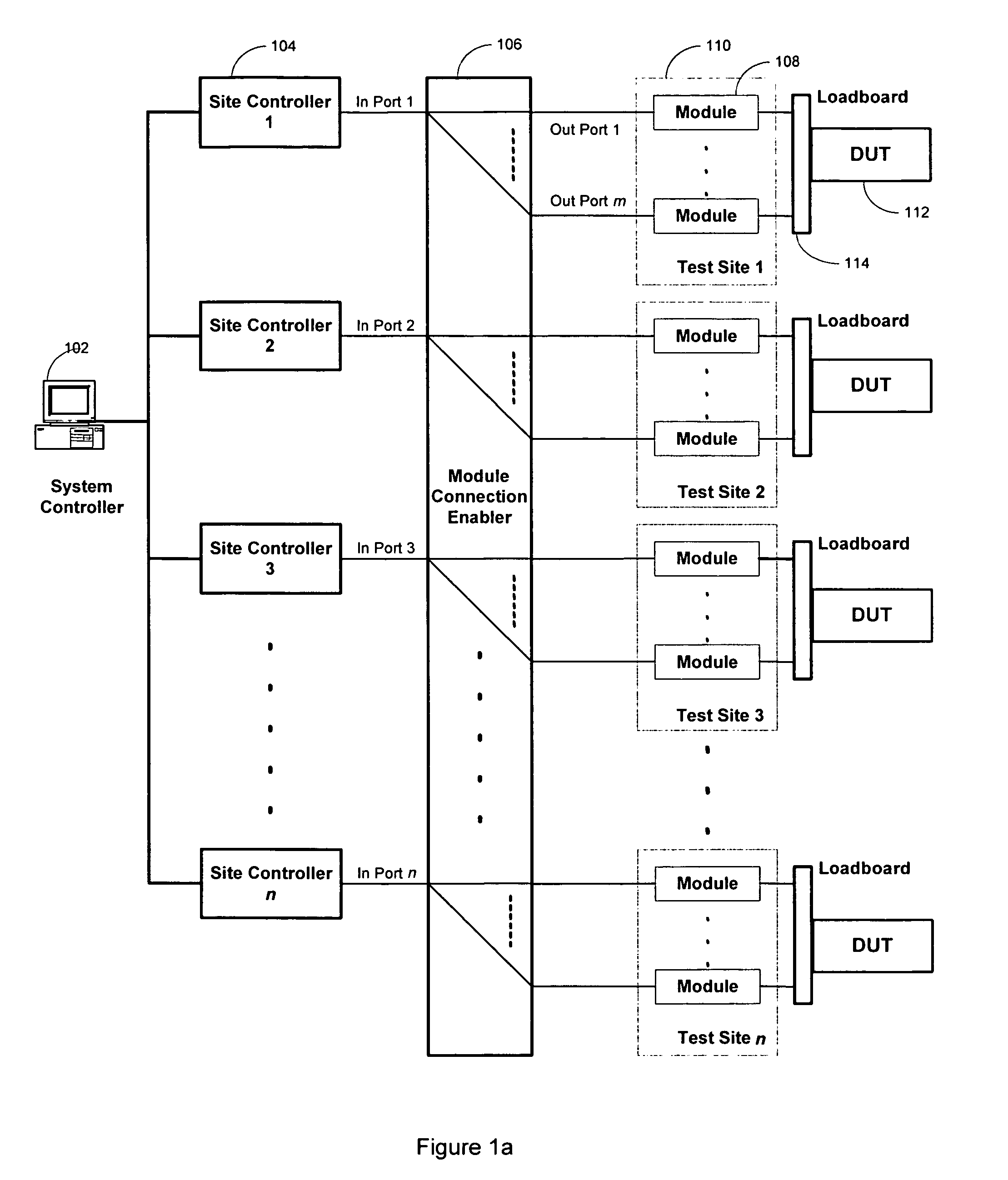
[0019]FIG. 1a illustrates an open architecture test system according to an embodiment of the present invention. A system controller (SysC) 102 is coupled to multiple site controllers (SiteCs) 104. The system controller may also be coupled to a netw...


PUM


Abstract

A method for simulating a modular test system is disclosed. The method includes providing a controller, where the controller controls at least one vendor module and its corresponding device under test (DUT) model, creating a simulation framework for establishing standard interfaces between the at least one vendor module and its corresponding DUT model, configuring the simulation framework, and simulating the modular test system using the simulation framework.

Description

CROSS-REFERENCE TO RELATED APPLICATIONS[0001]This application claims the benefit of provisional application No. 60 / 573,577, “Software Development in an Open Architecture Test System,” filed by Advantest Corporation on May 22, 2004, which is incorporated herein in its entirety by reference.FIELD OF THE INVENTION[0002]The present invention relates to the field of automated test equipment (ATE). In particular, the present invention relates to a method and system for simulating a modular test system.BACKGROUND OF THE INVENTION[0003]A major cost in semiconductor production is the development and maintenance of test programs that test integrated circuits for viability and functionality. This activity usually entails many hours of work on the actual tester hardware. However, existing semiconductor testers have little or no capability for simulating test programs, except for checking the semantics of the test programming language. This limitation forces engineers to debug their test program...

Claims


Application Information

Patent Timeline
Patent Type & Authority Patents(United States)
IPC IPC(8): G01R31/3183G01R31/42G01R31/319G06F11/26G06F17/50
CPCG01R31/318342G01R31/31907G01R31/319G01R31/3183G06F11/26
Inventor MUKAI, CONRADPRAMANICK, ANKANELSTON, MARKADACHI, TOSHIAKICHEN, LEON L.
Owner ADVANTEST AMERICA R & D CENT
Learn More