Bit synchronization for high-speed serial device testing

Active Publication Date: 2006-11-02
CREDENCE SYSTEMS
View PDF5 Cites 35 Cited by
  • Summary
  • Abstract
  • Description
  • Claims
  • Application Information

AI Technical Summary

Benefits of technology

[0009] The present invention provides a bit synchronization method used in testing electronic devices, referred to as an eye centering method, that is faster than the binary search method and does not require the use of time sets. Another advantage of the bit synchronization method according to the present invention is that it does not require mat

Problems solved by technology

This is important, because the bit stream produced by the device under test, especially high-speed serial devices, can be very non-deterministic during initialization, and discerning the difference between an out-of-position strobe data and properly strobed data becomes very difficult.

Method used


Image

  • Bit synchronization for high-speed serial device testing
  • Bit synchronization for high-speed serial device testing
  • Bit synchronization for high-speed serial device testing

Examples


Embodiment Construction

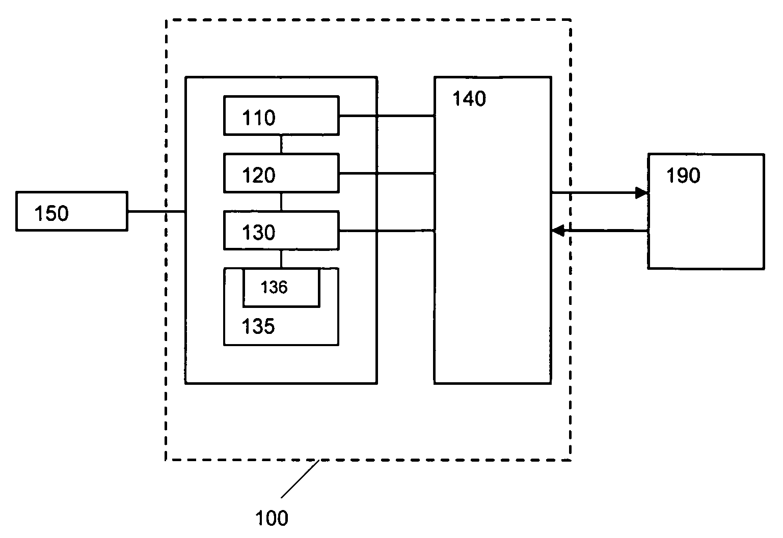
[0020]FIG. 1 shows a block diagram of a tester 100 in which an eye centering method according to an embodiment of the invention may be carried out. The tester 100 includes a number of slots in which a number of instruments are inserted. The instruments may include a device power supply (DPS) 110 for supplying power to a device under test (DUT) 190, analog test instruments 120 for supplying test signals to input analog pins of the DUT 190 and receiving response signals from output analog pins of the DUT 190, digital test instruments 130 for supplying test signals to input digital pins of the DUT 190 and receiving response signals from output digital pins of the DUT 190, a test head interface 135 which houses a master clock 136, and a fixture 140, known in the art as a loadboard, for providing a connection interface between the instruments 110, 120, 130 and the DUT 190. During testing, the tester 100 operates under the control of software, e.g., a test program 150. The bus architectur...


PUM


Abstract

An apparatus for testing electronic devices employs a programmable device to adjust the timing of the strobes such that the strobes sample the bit stream from a device under test at or near the center of the bit position. The strobe time adjustment is performed based on pairs of strobe readings made around a number of different bit positions. The programmable device examines the pairs of strobe reading made around each of the different bit positions to determine whether or not a bit transition has occurred there. The programmable device selects the bit positions around which a bit transition has not occurred as eye candidates, and defines the center of the largest contiguous region of eye candidates as the center of the bit position.

Description

BACKGROUND OF THE INVENTION [0001] 1. Field of the Invention [0002] The present invention relates generally to electronic device testing, and more particularly, to bit synchronization techniques used in testing integrated circuit (IC) devices that output high-speed serial data streams. [0003] 2. Description of the Related Art [0004] Next generation ICs will use a large number of high-speed serial links to communicate with external memory and I / O devices. In order to obtain accurate test results of such devices, it is important that a continuous stream of bits (0's and 1's) outputted by them is consistently strobed near the center of the bit and away from the transitions between the bits. If the strobes are positioned near the bit transitions, inaccurate strobe readings (e.g., 0 strobed as a 1, or 1 strobed as a 0) might result and cause inaccurate test results. [0005] A conventional automated test equipment (ATE) uses a binary search method to locate the center of the bit. The binar...

Claims


Application Information

Patent Timeline
IPC IPC(8): G11C8/00
CPCG11C29/56G11C2029/5602G11C29/56012
Inventor SAKAITANI, KRIS
Owner CREDENCE SYSTEMS
Why Eureka
Try Eureka