Test component and method of operation thereof

a technology of test components and components, applied in the field of test components, can solve the problems of increasing the complexity of the system, the number of states in a given design at any time, and the clear cost of performing test procedures on the componen

Active Publication Date: 2004-12-02
ARM LTD
View PDF5 Cites 36 Cited by
  • Summary
  • Abstract
  • Description
  • Claims
  • Application Information

AI Technical Summary

Problems solved by technology

It would clearly be very costly to perform test procedures on the component once it has actually been reduced to hardware, and instead rigorous testing of the RTL representation of the component is typically performed to ensure that the actual hardware generated from that RTL representation will operate correctly.
As designs increase in complexity, the number of states in a given design at any time increases exponentially.
As systems increase in complexity, for example in the above mentioned multi-layer systems, then a number of issues arise.
Firstly, the writing of directed test sequences for such systems is not only time consuming, but also simulation intensive and prone to error, such as, for example, may result from misconfiguration of a BFM.
Secondly, the test sequence has low re-usability, and is tightly coupled with the functional coverage required for the particular test environment.
Finally, the flexibility of the approach is limited since, considering an example where a particular processor model is used as the test component for testing the DUT, the available bus transactions may be limited to a subset of the transactions that are actually supported by the bus.
It is not possible to dynamically modify the behaviour of the component.
Hence, it is clear that existing techniques give rise to a number of problems, particularly as design complexity increases.
In particular, if specific test sequences are written for a particular DUT within a particular test environment, this is very time consuming, and results in large test stimulus files.
In addition, it has low re-usability.
If instead re-usable test components are provided within the test environment to generate random test sequences, this reduces the time involved in generating specific test sequences, and reduces the size of the stimulus files, but results in test sequences which by their nature are random and do not reflect the actual activities that would be expected within the "real" system.
Although directed-random burst transfers to a defined memory region are useful in this context, it is not possible to exactly specify the type and distribution patterns of the generated bursts.
Accordingly, in summary, it can be seen that whilst it is known to provide reusable test components such as BFMs for use in generating test sequences for a DUT, the known techniques for generating pseudo-random test sequences from such test components do not provide testing that accurately reflects the behaviour of the real system.
Whilst the writing of specific test sequences can alleviate this problem, this is very time intensive, and results in large stimulus files which have low-reusability.
As design complexity increases, it becomes less and less attractive to write specific test sequences.

Method used


Image

  • Test component and method of operation thereof
  • Test component and method of operation thereof
  • Test component and method of operation thereof

Examples


Embodiment Construction

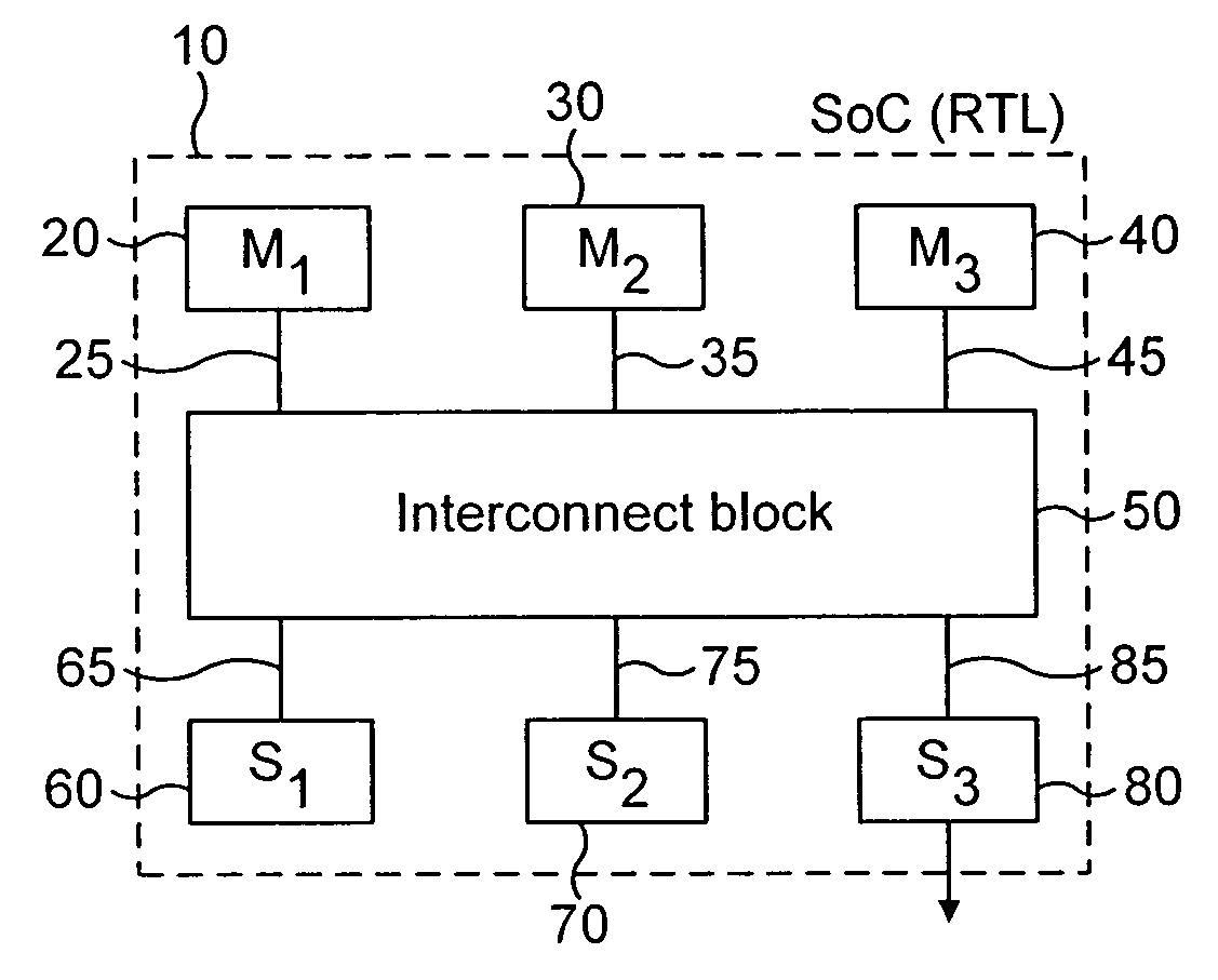
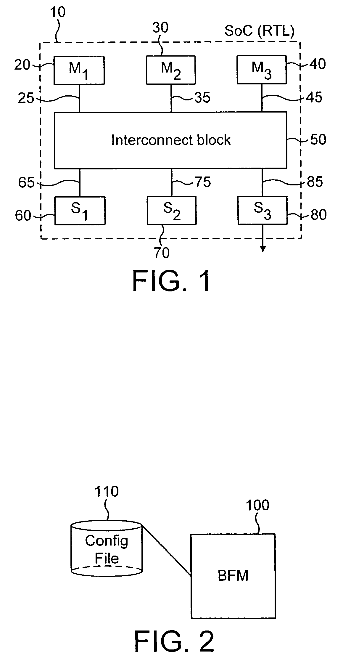
[0070] Before discussing in detail the testing procedures of embodiments of the present invention, an example of the design of a data processing apparatus for which these testing procedures can be utilised will be discussed with reference to FIG. 1.

[0071] FIG. 1 illustrates the design 10 of a data processing apparatus taking the form of a microcontroller chip or System on Chip (SoC), which may be used within a device such as a personal organiser, a mobile phone, a television set top box etc. The SoC design 10 of FIG. 1 has a plurality of components 20, 30, 40, 60, 70 and 80 that are interconnected by an arrangement of buses. The actual interconnection of these buses is specified within the interconnect block 50. The interconnect block 50 includes a bus matrix which provides for the interconnection of multiple bus masters and slaves within the SoC 10. Hence, each master device 20, 30, 40 may be connected to corresponding buses 25, 35, 45 respectively, whilst each slave device 60, 70,...


PUM


Abstract

A test component and method of operation thereof are provided, the test component being arranged in a test environment to issue a test sequence over a bus to a device under test. A configuration file is provided to specify the behaviour of the test component, the configuration file comprising a plurality of regions with each region specifying attributes for use in determining the test sequence. A number of the regions specify constraint attributes defining allowable test sequences. The method of the present invention comprises the steps of: (a) when a test sequence is required to be issued, causing the test component to select, based on predetermined criteria, one of a number of regions provided by the configuration file; and (b) using the constraint attributes for that selected region to generate the test sequence to be issued on to the bus. It has been found that such an approach provides an efficient technique for enabling the test component to be configured to emulate the actual component which in the real system will interact with the device being tested. It has also been found that the time taken to write the tests required for the device under test is significantly reduced compared to prior art techniques.

Description

[0001] 1. Field of the Invention[0002] The present invention relates to test components used in a test environment to issue test sequences to a device to be tested, hereafter referred to as a "Device Under Test" (DUT).[0003] 2. Description of the Prior Art[0004] When developing components for integration into a system, a number of test procedures are typically performed to ensure that the component will operate in the desired manner when integrated into the system.[0005] The development of a hardware component (also referred to herein as a device) typically takes place in a number of stages. Firstly, the functional operation / behaviour of the component is defined, for example using a Register Transfer Language (RTL). Two popular RTLs used are VHDL and Verilog. In addition, prior to performing such RTL coding, a behavioural model may be built, for example using "System C", to validate at a transactional level that the design intent is correct.[0006] Once an RTL representation of the h...

Claims


Application Information

Patent Timeline
Patent Type & Authority Applications(United States)
IPC IPC(8): G01M99/00H04L12/26
CPCH04L12/2697H04L43/50
Inventor WRIGLEY, CHRISTOPHER E.COLEY, DANIEL J.NIGHTINGALE, ANDREW M.
Owner ARM LTD
Why Eureka
Try Eureka