
Decoder and decoding method for decoding low-density parity-check codes with parity check matrix

Inactive Publication Date: 2006-01-05
KK TOSHIBA
View PDF4 Cites 13 Cited by
  • Summary
  • Abstract
  • Description
  • Claims
  • Application Information

AI Technical Summary

Benefits of technology

[0091] Additional advantages and modifications will readily occur to those skilled in the art. Therefore, the invention in its broader aspects is not limited to the specific details and representative embodiments shown and described herein. Accordingly, various modifications may be made without departing from the spirit or scope of the general inventive concept as defined by the appended claims and their equivalents.

Problems solved by technology

Therefore, in the prior art, parity update computation of one loop cannot be started unless bit update computation of one loop is finished, and bit update computation of the next loop cannot be started unless parity update computation of the one loop is finished.

Method used


Image

  • Decoder and decoding method for decoding low-density parity-check codes with parity check matrix
  • Decoder and decoding method for decoding low-density parity-check codes with parity check matrix
  • Decoder and decoding method for decoding low-density parity-check codes with parity check matrix

Examples


Embodiment Construction

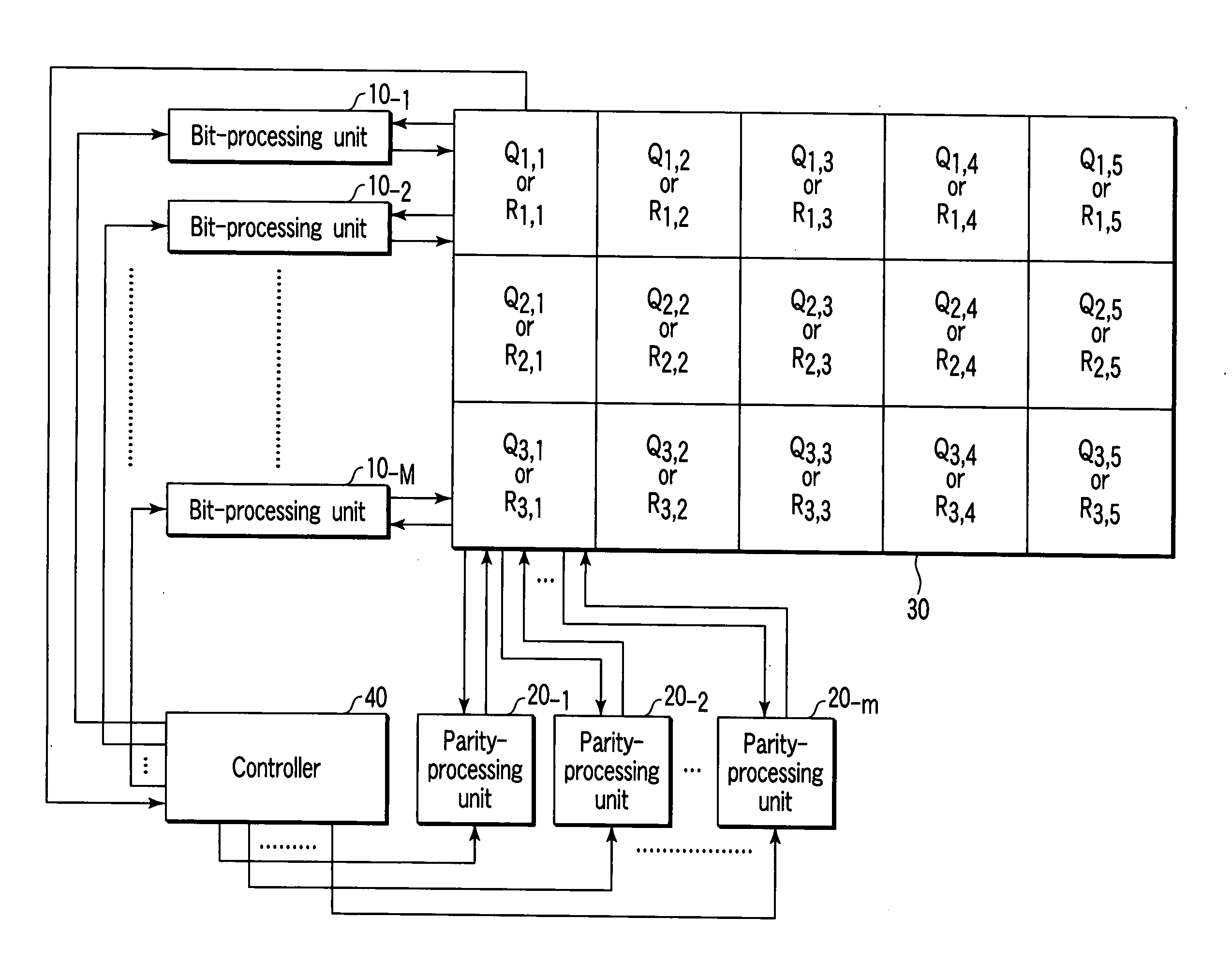
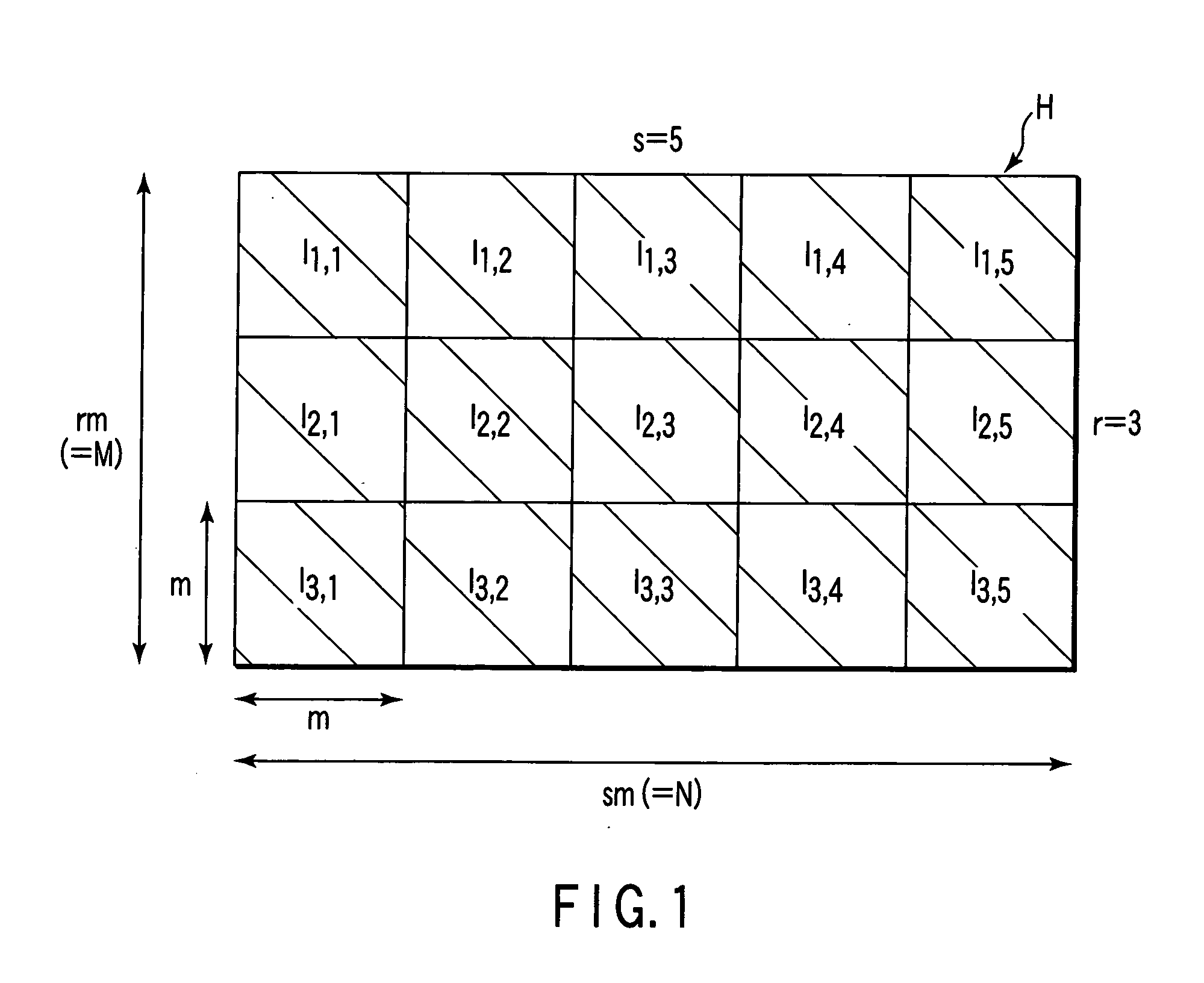
[0016] An embodiment of the invention will be described with reference to the accompanying drawings. Firstly, a description will be given of a parity-check matrix H of low-density parity-check codes (LDPC codes) employed in the embodiment. As shown in FIG. 1, the parity-check matrix H is an array of (r×s) permuted matrices Ig,h (g=1, 2, . . . , r; h=1, 2, . . . , s). Each permuted matrix Ig,h is a sub-matrix of the check matrix H. Each permuted matrix Ig,h is acquired by iterating, a number of times, exchange of two different rows or columns included in unit matrices I each having an array of (m×m). In this case, the number M of rows of the check matrix H is rm, and the number N of columns of the matrix H is sm. In the example of FIG. 1, r=3 and s=5. Further, the check matrix H is divided into s column blocks (i.e., the 1st to the sth column blocks). Permuted matrices I1,h, I2,h and I3,h belong to the hth column block.

[0017] The check matrix H contains M (=rm) parity nodes, and N (...


PUM


Abstract

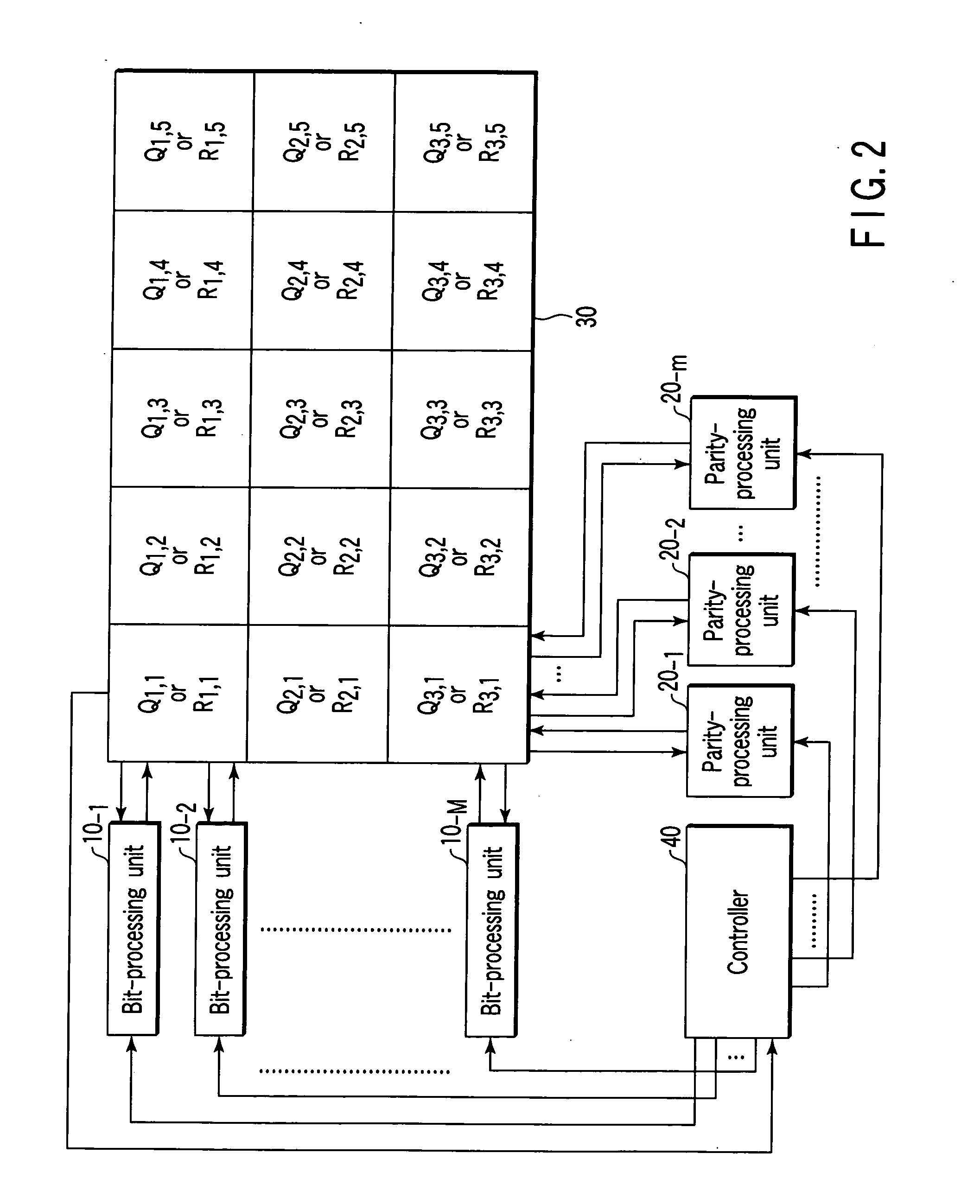
In an LDPC-code decoder, bit-processing units are provided, respectively, for the 1st to Mth rows of the parity-check matrix that is formed of (r×s) permuted matrices having respective arrays of (m×m) Each of bit-processing units sequentially updates bit information corresponding to column positions included in the respective rows of the parity-check matrix, a bit at each of the column positions being set to “1”. parity-processing units update parity information corresponding to row positions in columns of each column block of the parity-check matrix, whenever the bit-processing units have finished bit update computation for m column positions in each column block, a bit at each row position being set to “1”. The bit-processing units starts next bit update computation after the parity-processing units finish parity update computation for m columns of the first column block of the parity-check matrix.

Description

CROSS-REFERENCE TO RELATED APPLICATIONS [0001] This application is based upon and claims the benefit of priority from prior Japanese Patent Application No. 2004-193767, filed Jun. 30, 2004, the entire contents of which are incorporated herein by reference. BACKGROUND OF THE INVENTION [0002] 1. Field of the Invention [0003] The present invention relates to a decoder and decoding method for decoding low-density parity-check codes with parity check matrices. [0004] 2. Description of the Related Art [0005] Attention has recently been paid to low-density parity-check codes (LDPC codes) used as error detection and correction codes. Message-passing algorithms are known as a technique for decoding LDPC codes from, for example, Andrew J. Blanksby and Chris J. Howland, “A 690-mW 1-Gb / s 1024-b, Rate-½ Low-Density Parity-Check Code Decoder”, IEEE Journal of Solid-State Circuits, Vol. 37, No. 3, pp. 404-412, March 2002. In the message-passing algorithms, to decode LDPC codes, bit update computat...

Claims


Application Information

Patent Timeline
IPC IPC(8): H03M13/00G11C29/00H03M13/11
CPCH03M13/1137H03M13/114H03M13/1168H03M13/116H03M13/19H03M13/11
Inventor YOSHIDA, KENJI
Owner KK TOSHIBA
Learn More