Handle for a Handheld Working Tool

Inactive Publication Date: 2006-01-12
ANDREAS STIHL AG & CO KG
View PDF15 Cites 9 Cited by
  • Summary
  • Abstract
  • Description
  • Claims
  • Application Information

AI Technical Summary

Benefits of technology

[0017] In an advantageous embodiment, the handle pipe has distinctly curved sections as well as fastening sections that are reinforced by the corresponding reinforcement elements, respectively. It was found that the aforementioned areas are subject to high dynamic bending strain, lateral force loads, and torsional loads; the resonant frequency of the vibration system can be raised in a targeted fashion by a targeted reinforcement in these areas. The further areas of the handle pipe can remain free of reinforcement. Additional masses in this area as well as thickening of the cross-section therefore are

Problems solved by technology

When operating a handheld working tool (power tool), such as a motor chainsaw, a trimmer or the like, mechanical vibrations occur that can be caused by the running o

Method used


Image

  • Handle for a Handheld Working Tool
  • Handle for a Handheld Working Tool
  • Handle for a Handheld Working Tool

Examples


Embodiment Construction

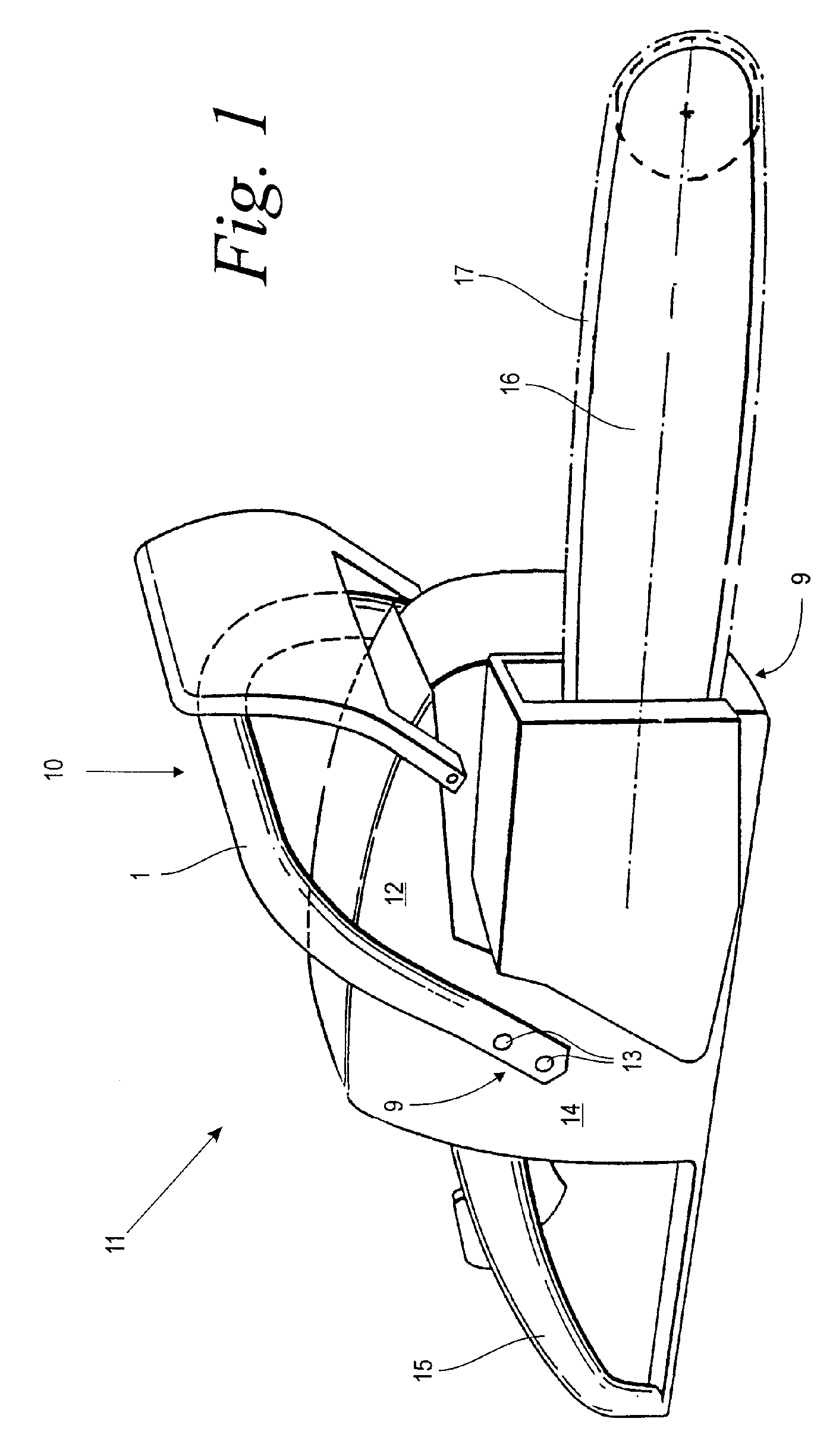
[0030]FIG. 1 shows a perspective illustration of a handheld working tool 11 shown in an exemplary embodiment as a motor chainsaw. The working tool 11 has a motor housing 14 in which a drive motor 12, not shown in detail, is arranged. A guide bar 16 projects from the motor housing 14; a saw chain 17 driven by the drive motor 12 is guided in circulation about the guide bar 16. A rear handle 15 is arranged at the rear area of the motor housing 14 opposite the guide bar 16. A front handle 10 comprises a handle pipe or handle tube 1 that partially surrounds the motor housing 14 near the center of gravity. The handle pipe 1 has two fastening sections 9 arranged at a lateral surface of the motor housing 14 and in the area of the bottom of the working tool 11; the handle pipe 1 is attached by means of screws 13 with the fastening sections to the motor housing 14.

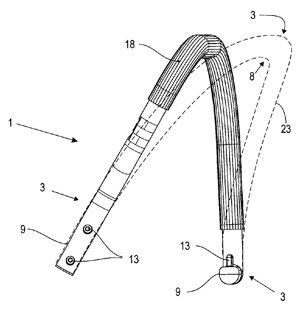
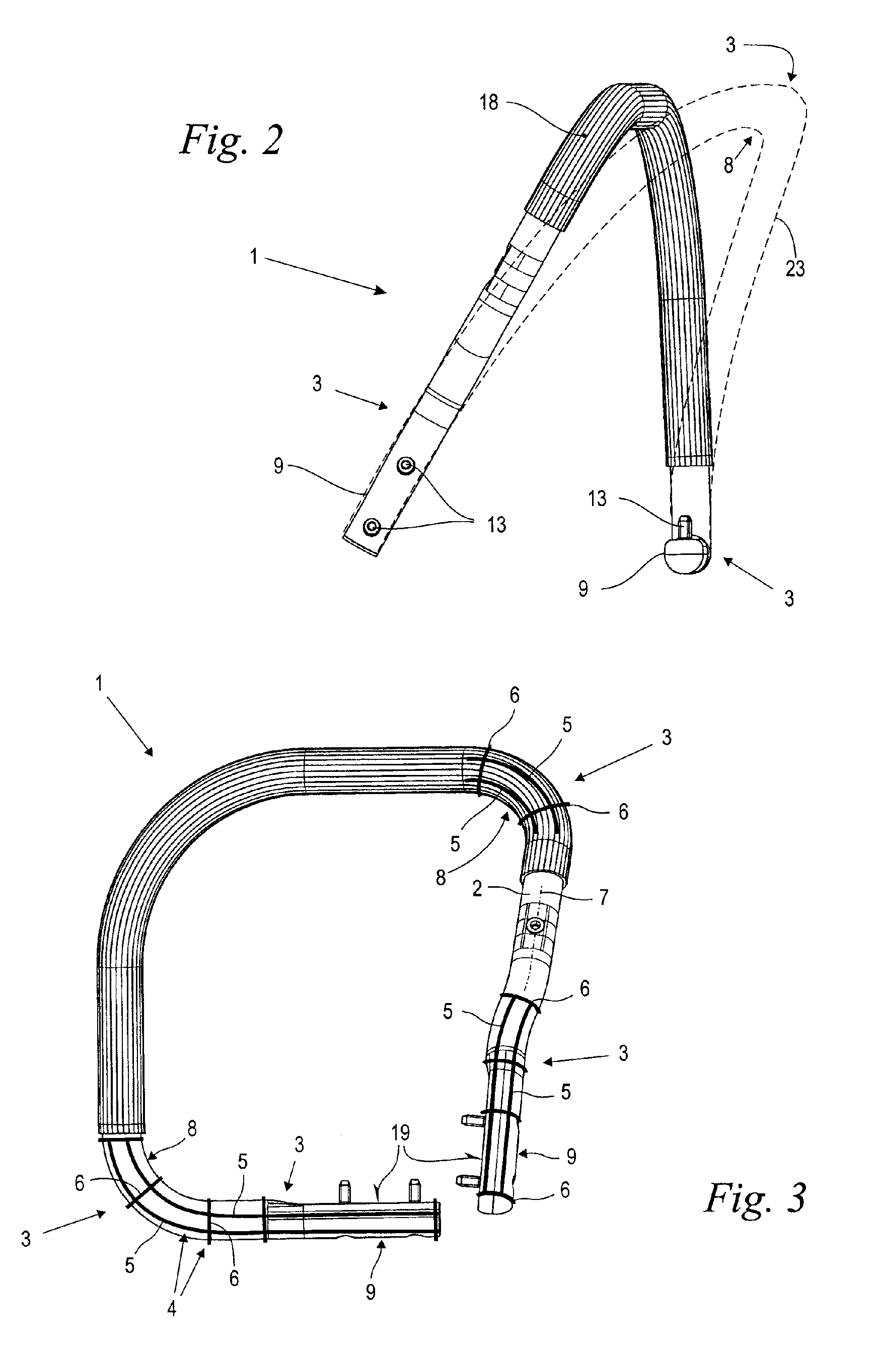
[0031]FIG. 2 shows in a side view details of the handle pipe 1 according to FIG. 1. The handle pipe 1 is covered by a grip hose 1...


PUM


Abstract

A handle of a handheld working tool has a handle pipe reinforced by at least one reinforcement element locally arranged on the handle pipe at a location of high dynamic vibration-caused deformation energy. The handle pipe and the reinforcement element are made of plastic material. A laminate that is made of fiber-reinforced plastic material can be used for making the handle.

Description

BACKGROUND OF THE INVENTION [0001] The invention relates to a handle of a handheld working tool, such as a motor chain saw or the like, comprising a handle pipe. The invention further relates to a working tool comprising such a handle. [0002] When operating a handheld working tool (power tool), such as a motor chainsaw, a trimmer or the like, mechanical vibrations occur that can be caused by the running of a drive motor or by the driven cutting tool. The working tool (power tool) is held by a handle and guided during operation of the tool by means of the handle. The mass of the working tool forms together with the elastically deformable handle a vibratory system that can be excited by the exciting vibrations of the motor or the cutting tool. These vibrations can be felt by the operator's hand that grips the handle and guides the tool. Excessive vibrations can cause the operator to experience untimely fatigue or can lead to an unsatisfactory work result. [0003] Numerous designs of vi...

Claims


Application Information

Patent Timeline
IPC IPC(8): B25G1/10B25F5/02B25G1/01
CPCB25F5/02Y10T16/476B25G1/102B25G1/01
Inventor KEMMLER, RALF-RAINERKANDZIORA, BERTRAM
Owner ANDREAS STIHL AG & CO KG
Why Eureka
Try Eureka