Four stroke engine auto-ignition combustion

a combustion engine and gasoline technology, applied in the direction of machines/engines, electrical control, output power, etc., can solve the problems of high nox emissions, high nox emissions, and the limit at which an engine can be operated with a diluted mixtur

Active Publication Date: 2006-01-12
GM GLOBAL TECH OPERATIONS LLC
View PDF11 Cites 17 Cited by
  • Summary
  • Abstract
  • Description
  • Claims
  • Application Information

AI Technical Summary

Benefits of technology

[0014] The present invention presents a method for operating a four-stroke gasoline direct-injection controlled auto-ignition combustion engine at low speed and load including idle with acceptable torque fluctuation. The method consists of double opening of both intake and exhaust valves and a split injection strategy with equal amount of fuel split. Supplemental means for controlling air delivery may also be included.
[0015] These and other features and advantages of the invention will be more fully understood from the following description of certain specific embodiments of the invention taken together with the accompanying drawings.

Problems solved by technology

However, there is a limit at which an engine can be operated with a diluted mixture because of misfire and combustion instability as a result of a slow burn.
In both spark ignition and diesel engines, the burned gas temperatures are highly heterogeneous within the mixture with very high local temperatures creating high NOx emissions.
In four-stroke engines with traditional valve means, the residual content is low and controlled auto-ignition at part load is difficult to achieve.
In all the above methods, the range of engine speeds and loads in which controlled auto-ignition combustion can be achieved is relatively narrow.
However, torque fluctuation increases during idle and low load engine operations may be a concern.

Method used


Image

  • Four stroke engine auto-ignition combustion
  • Four stroke engine auto-ignition combustion
  • Four stroke engine auto-ignition combustion

Examples


Embodiment Construction

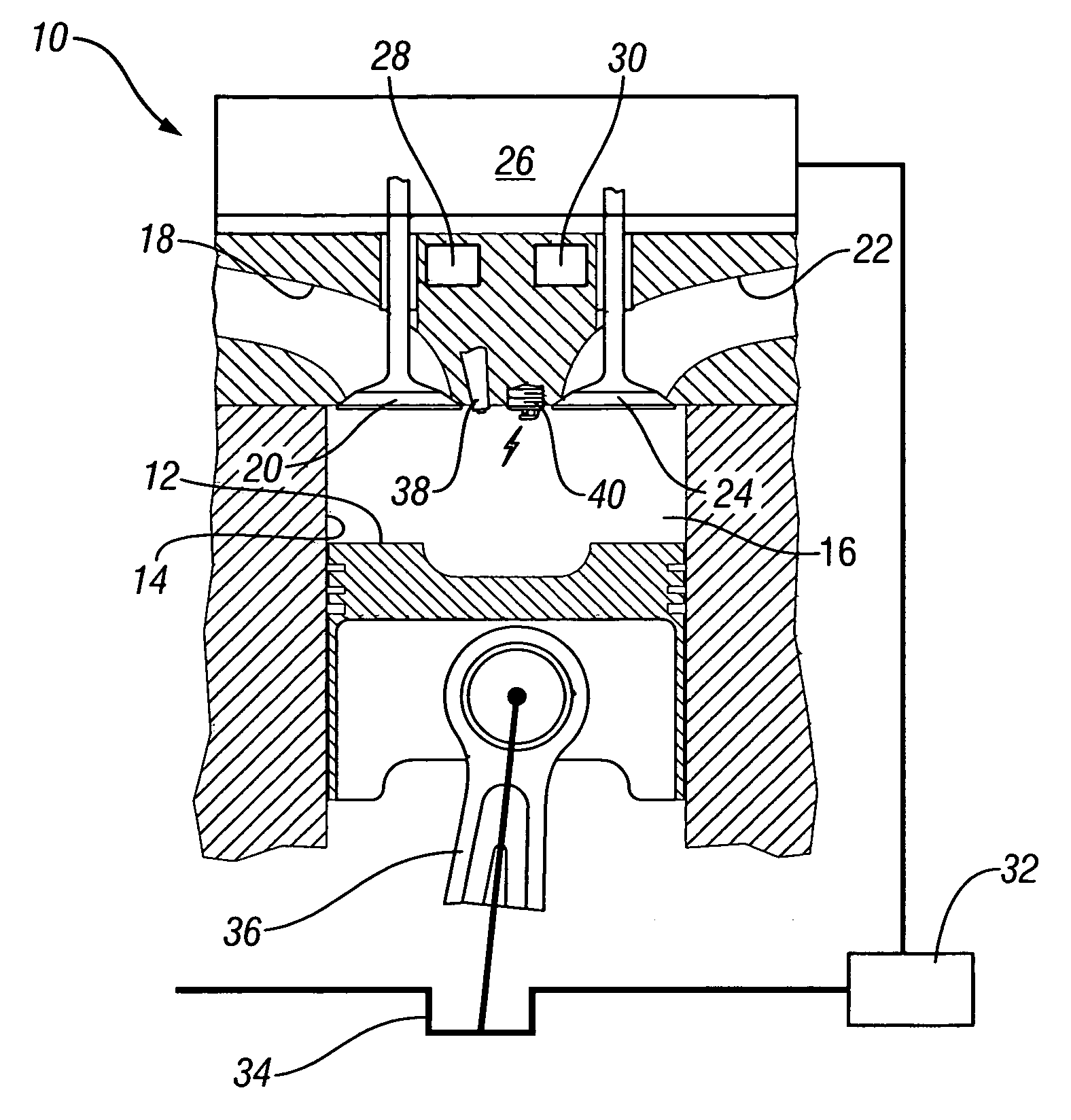
[0027] For simplicity, the following descriptions will address the present invention in its application to a single cylinder direct-injection gasoline four-stroke internal combustion engine, although it should be appreciated that the present invention is equally applicable to a multi-cylinder direct-injection gasoline four-stroke internal combustion engine.

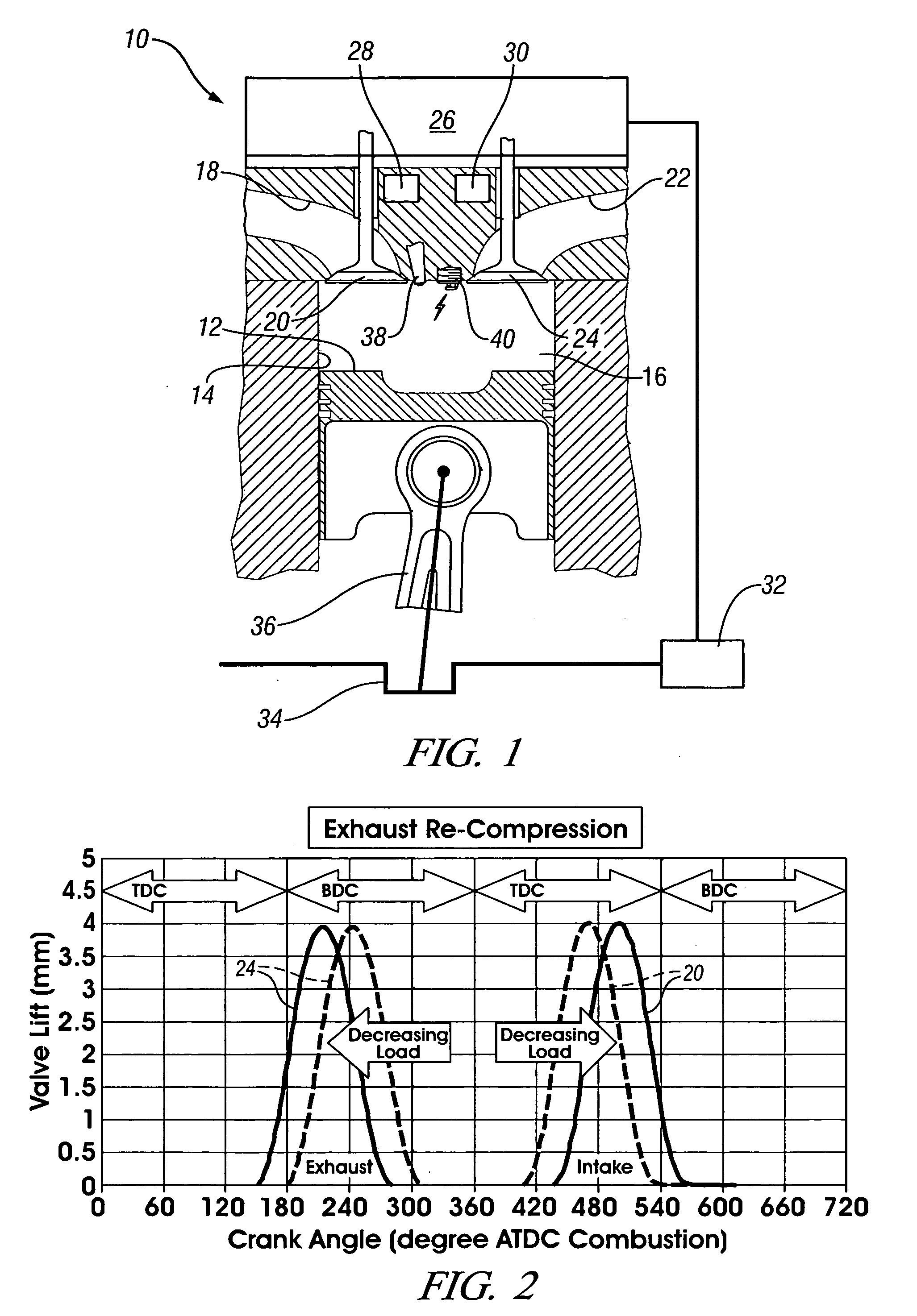
[0028] A schematic representation of a first embodiment of single-cylinder direct-injection four-stroke internal combustion engine 10 is given in FIG. 1. In the figure a piston 12 is movable in a cylinder 14 and defines with the cylinder 14 a variable volume combustion chamber 16. An intake passage 18 supplies air into the combustion chamber 16. Flow of air into the combustion chamber 16 is controlled by an intake valve 20. Combusted gases can flow from the combustion chamber 16 via an exhaust passage 22 and flow of combusted gases through the exhaust passage 22 is controlled by an exhaust valve 24.

[0029] The engine 10, as shown...


PUM


Abstract

A method of operating a four-stroke gasoline direct-injection controlled auto-ignition combustion engine includes opening both the intake and exhaust valves during terminal portions of the expansion strokes and initial portions of the contraction strokes, injecting fuel directly into the combustion chamber for mixing with retained gases and igniting the fuel near the ends of the contraction strokes. In the process, combustion gases are expanded to produce power during major portions of the expansion strokes, combusted gases are blown down into the exhaust outlet and the air inlet and are partially redrawn into the cylinder with fresh air during the terminal portions of the expansion strokes so the air charges are heated by the hot exhaust gases. Portions of the charges re-expelled and the remaining portions of the charges and injected fuel are compressed for ignition of the dilute fuel/air and exhaust gas mixture. Substantial reductions of NOx emissions result from the method.

Description

CROSS REFERENCE TO RELATED APPLICATIONS [0001] This application claims priority from U.S. Provisional Patent Application No. 60 / 587,101 filed Jul. 12, 2004.TECHNICAL FIELD [0002] The present invention presents a method for operating a four-stroke gasoline direct-injection controlled auto-ignition combustion engine, at least at low speed and load including idle BACKGROUND OF THE INVENTION [0003] To improve thermal efficiency of gasoline internal combustion engines, dilute combustion—using either air or re-circulated exhaust gas—is known to give enhanced thermal efficiency and low NOx emissions. However, there is a limit at which an engine can be operated with a diluted mixture because of misfire and combustion instability as a result of a slow burn. Known methods to extend the dilution limit include 1) improving ignitability of the mixture by enhancing ignition and fuel preparation, 2) increasing the flame speed by introducing charge motion and turbulence, and 3) operating the engine...

Claims


Application Information

Patent Timeline
Patent Type & Authority Applications(United States)
IPC IPC(8): F02B69/06F02B75/02F02M25/07F02B75/20
CPCF02B17/005F02B19/02F02D13/0207F02D13/0265Y02T10/18F02D41/402F02M25/0752Y02T10/125Y02T10/42F02D41/3035F02M26/01Y02T10/12Y02T10/40
Inventor KUO, TANG-WEIENG, JAMES A.NAJT, PAUL M.BROWN, BARRY L.
Owner GM GLOBAL TECH OPERATIONS LLC
Why Eureka
Try Eureka