
Filter arrangement for fuel injection systems

a filter arrangement and fuel injection technology, applied in the direction of machine/engine, fuel injection apparatus, charge feed system, etc., can solve the problems of not inconsiderable pressure loss, impair the maximum injection pressure, and worsen the system efficiency, so as to increase the efficiency of the fuel injection system

Inactive Publication Date: 2006-01-12
ROBERT BOSCH GMBH
View PDF9 Cites 16 Cited by
  • Summary
  • Abstract
  • Description
  • Claims
  • Application Information

AI Technical Summary

Benefits of technology

[0007] In fuel injection systems that include both a high- pressure connection and pressure booster which is controlled by subjecting a differential pressure chamber to pressure or relieving that chamber of pressure, it is possible according to the invention to integrate a filter element in such a way that during the injection, no throttling losses that impair the attainable maximum injection pressure occur. Thus the actual maximum injection pressure, at which the fuel is injected into the combustion chamber of the engine, can be increased. An increase in the efficiency of the fuel injection system is also attainable.
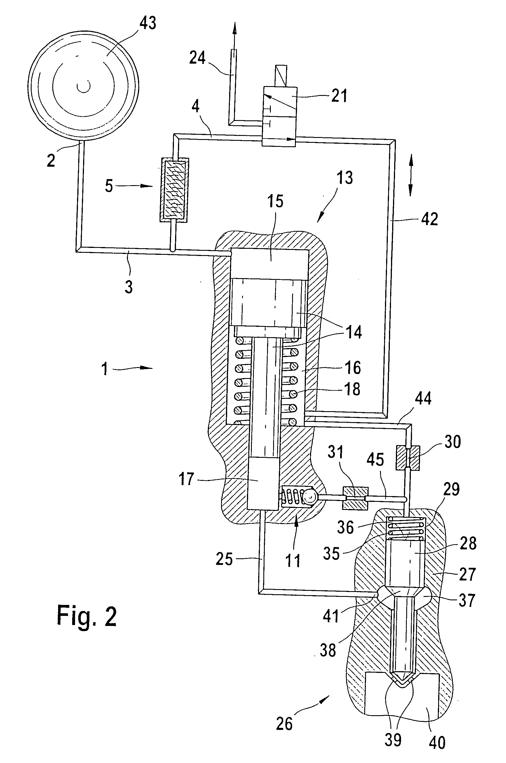
[0009] In a first variant embodiment, the filter element can be made to be located upstream of flow connections by way of which a differential pressure chamber of the pressure booster and its high-pressure chamber are re-filled with fuel in the restoration phase of a boosting element received in the pressure booster and configured in pistonlike fashion. This assures that the fuel, compressed by a in accordance with the boosting ratio of the pressure booster, that flows out into the fuel injector is free of contaminants, so that all the vulnerable throttles, valve cross sections, and in particular the valve seats are protected. This applies to all the regions of the fuel injector located downstream of the pressure booster.
[0010] Alternatively, the filter element can be disposed upstream of a switching valve that actuates the pressure booster. The filter element is integrated into the supply line to the switching valve in such a way that all the regions of the fuel injector, except for the work chamber of the pressure booster, are supplied with filtered fuel. Moreover, the switching valve, which may have sealing seats and, in a servo-hydraulic version, also throttles with very small throttle cross sections, can be protected against contaminants.
[0012] As a result, there are no throttling losses during the injection, and all the vulnerable, close-tolerance components of the fuel injector are effectively protected against damage and leaks from deposits of particles. In a space-saving variant, the filter element, a check valve in the bypass line of the pressure booster, a throttle restriction, and a filling valve can all be integrated with the boosting element of the pressure booster.

Problems solved by technology

A disadvantage of the use of rod filters in fuel injectors of fuel injection systems that include a high- pressure reservoir and a pressure boosting unit to increase the pressure level is the high volumetric flow of fuel that flows from the high-pressure reservoir to the fuel injector during the brief injection phase.
As a result, severe throttling occurs when filter elements embodied as rod filters are used, resulting in a not inconsiderable pressure loss.
This worsens the system efficiency and impairs the maximum injection pressure.
Yet relatively large rod filters cannot be accommodated in the installation space available.

Method used


Image

  • Filter arrangement for fuel injection systems
  • Filter arrangement for fuel injection systems
  • Filter arrangement for fuel injection systems

Examples


Embodiment Construction

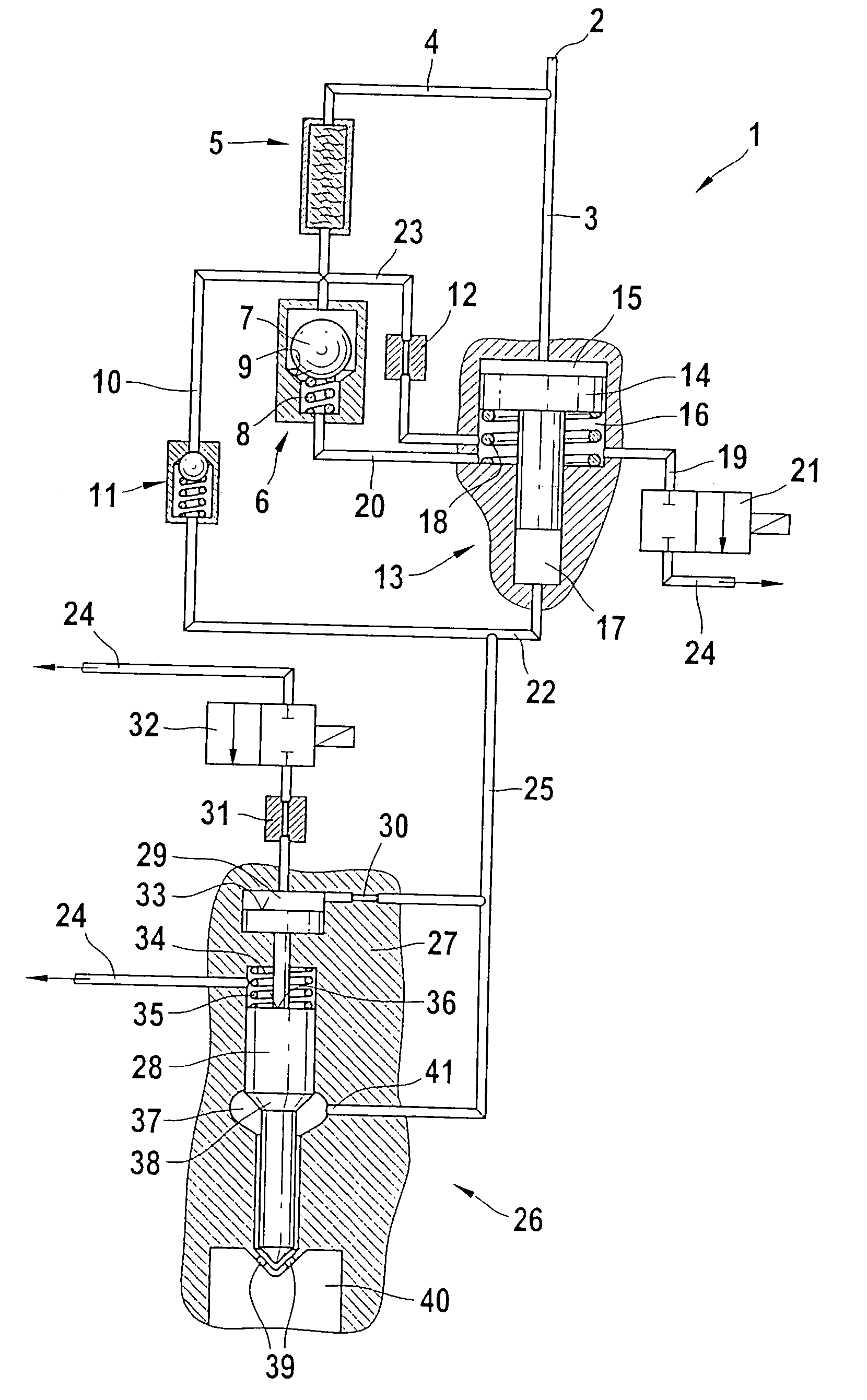
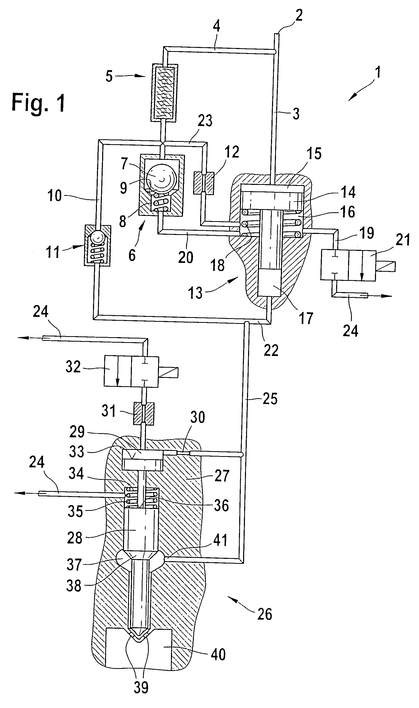
[0018]FIG. 1 shows the illustration of an exemplary embodiment in which a filter element is upstream of the filling lines of pressure chambers of a pressure booster.

[0019] From the illustration in FIG. 1, a fuel injection system 1 can be seen, which is acted upon, via a high- pressure source, not shown in FIG. 1, with fuel that is at high pressure. The high-pressure source not shown in the drawing is connected to a high-pressure connection 2 of a high-pressure line 3 and acts directly upon a work chamber 15 of a pressure booster 13, without throttling.

[0020] From the high-pressure line 3, a line portion 4 in which a filter element 5 is received branches off. In comparison to the volumetric flow of fuel that flows through the high-pressure line 3 to the work chamber 15 of the pressure booster 13, the fuel volume that passes through the line portion 4 is slight.

[0021] After passing through the filter element 5, the volumetric flow of fuel passing through the line portion 4 flows to...


PUM


Abstract

A fuel injection system for internal combustion engines, having a fuel injector that can be acted upon by a high-pressure fuel source includes a pressure booster, which contains a movable boosting element dividing a work chamber which can be made to communicate with the high-pressure source via a high-pressure line from a high-pressure chamber that acts on the fuel injector. The high-pressure from chamber is variable by filling and evacuating a differential pressure chamber of the pressure booster. A filter element is received in a line portion that branches off from the high-pressure line and is upstream of flow connections for filling the differential and high pressure chambers.

Description

FIELD OF THE INVENTION [0001] Both pressure-controlled and stroke-controlled injection systems can be used to supply combustion chambers of self-igniting internal combustion engines. Besides unit fuel injectors and pump-line units, reservoir injection systems (common rails) are also used. Common rails advantageously make it possible to adapt the injection pressure to the load and rpm of the engine. To achieve high specific outputs and to reduce emissions, the highest possible injection pressure is generally required. BACKGROUND OF THE INVENTION [0002] German Patent Disclosure DE 199 10 970 A1 relates to a fuel injection system. It has a pressure boosting unit which is disposed between a pressure reservoir and a nozzle chamber and whose pressure chamber communicates with the nozzle chamber via a pressure line. A bypass line connected to the pressure reservoir is also provided. The bypass line communicates directly with the pressure line. The bypass line can be used for a pressurized ...

Claims


Application Information

Patent Timeline
Patent Type & Authority Applications(United States)
IPC IPC(8): F02M57/02F02M47/02F02M59/10F02M61/16F02M63/00
CPCF02M47/027F02M57/025F02M63/0043F02M61/165F02M63/0015F02M59/105
Inventor MAGEL, HANS-CHRISTOPHKROPP, MARTIN
Owner ROBERT BOSCH GMBH
Learn More