Less smoke fume-dispersing device for welding operations

a fume-dispersing device and welding technology, applied in welding apparatus, manufacturing tools, evacuating shielding, etc., can solve the problems of long-term or permanent afflictions of the respiratory system, health and safety risks, and easy irritation of the eyes, respiratory system, etc., and achieve easy manufacturing, low cost, and easy market fume-dispersing

Inactive Publication Date: 2006-01-12
DEAN CHAD J
View PDF11 Cites 4 Cited by
  • Summary
  • Abstract
  • Description
  • Claims
  • Application Information

AI Technical Summary

Benefits of technology

[0011] It is an object of this invention to provide a low cost, easy to manufacture and easy to market fume-dispersing device. It is a further object of this invention to provide a fume-dispersing device that is not bulky, so that it may be employed even in tight work areas.

Problems solved by technology

With MIG and TIG welding, the shielding gas is typically argon, and this gas, sometimes along with other types of supplemental gases, accumulates within the work area, posing a health and safety risk.
Prolonged exposure to such gases can lead to persistent irritation of the eyes, respiratory system, and other organs, and, in some cases, to long-term or permanent afflictions of these organs and systems.
Although the prior art contains numerous fume and gas extracting devices for welding, they are generally elaborate in design and cumbersome to use, containing features that limit their practical use and flexibility in various welding applications.
Many of the devices can actually get in the way of the welding process, particularly in tight work areas.

Method used


Image

  • Less smoke fume-dispersing device for welding operations
  • Less smoke fume-dispersing device for welding operations
  • Less smoke fume-dispersing device for welding operations

Examples


Embodiment Construction

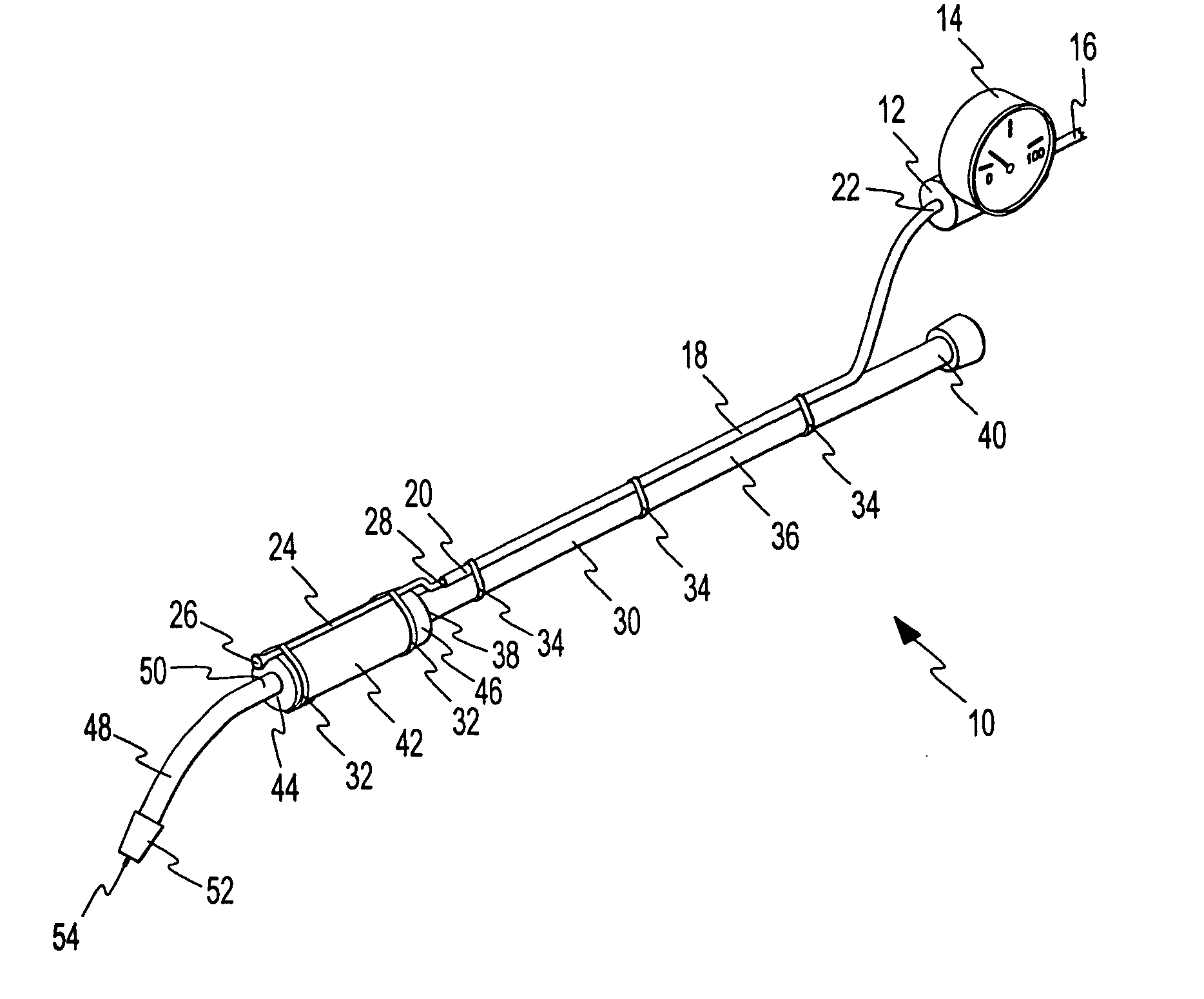
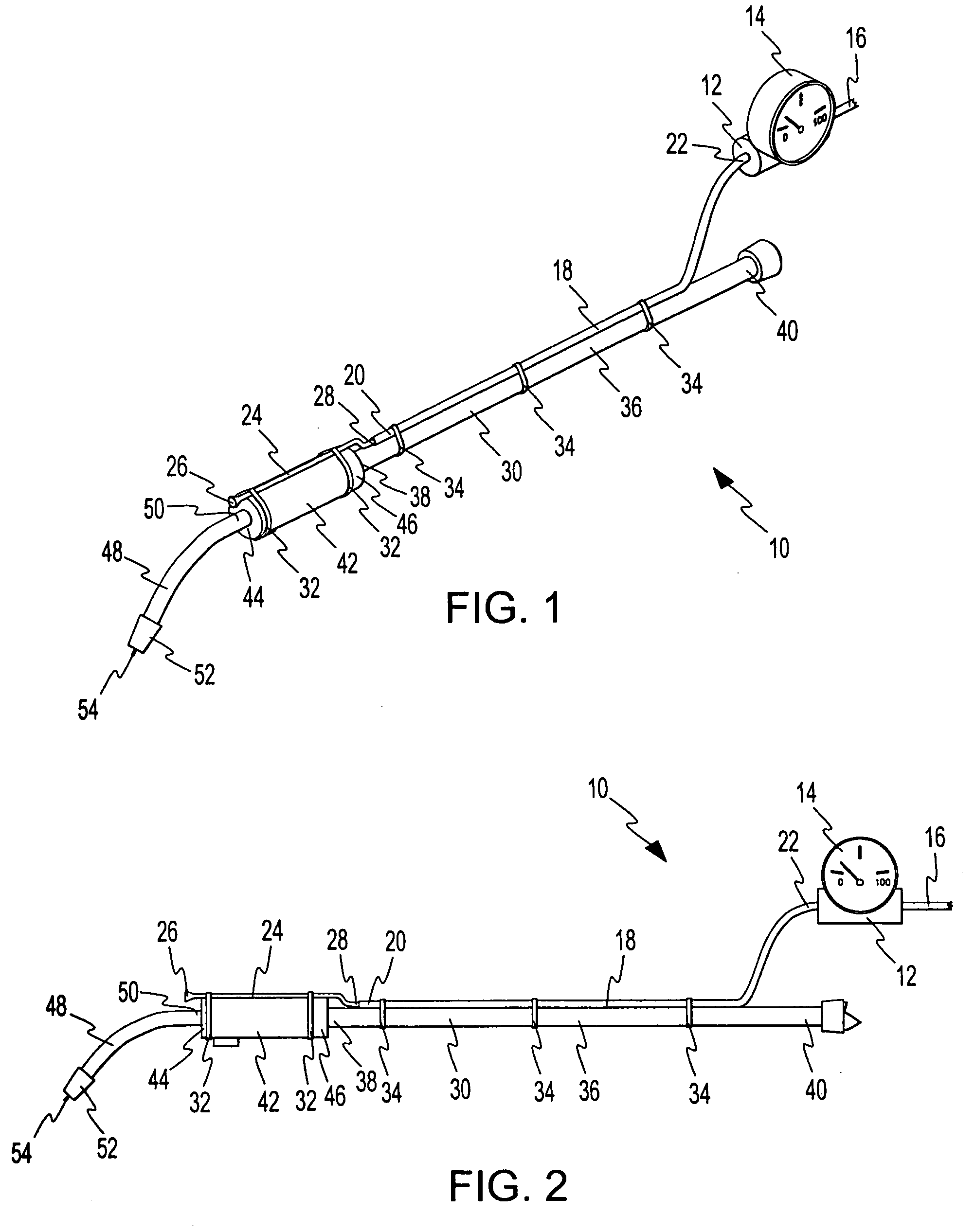
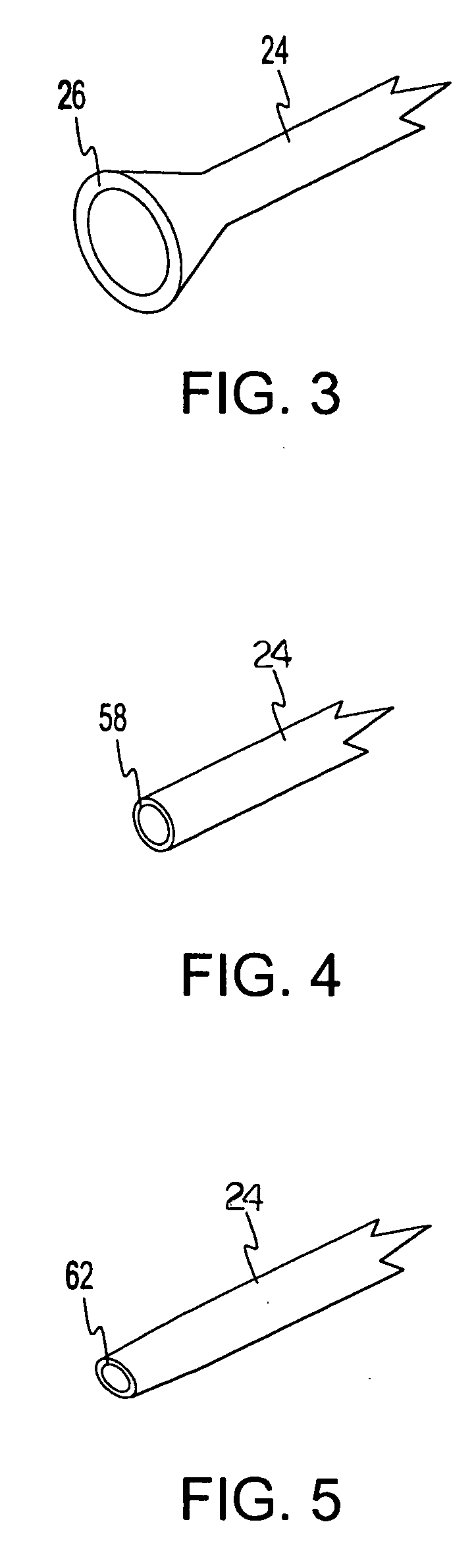
[0021] Referring now to FIGS. 1 and 2, an embodiment of a fume-dispersing device for a welder is shown and designated by the numeral 10. Device 10 includes air regulator 12, having gauge 14 and feed hose 16, which fluidly connects to a pressurized air source such as an air compressor (not shown). These are known items, and it will be appreciated that air regulator 12 can be employed to adjust the pressure of air being fed with feed tube 16, with gauge 14 providing a readout of the pressure. Air regulator 12 communicates with air hose 18, having outlet end 20 and inlet end 22. Outlet end 20 communicates with fume dispersion tube 24. Fume dispersion tube 24 includes open end 26 and inlet end 28, which is in fluid communication with outlet end 20 of air hose 18. Thus, pressurized air fed with feed hose 16 and air regulator 12 travels through air hose 18 and ultimately is expelled out of open end 26 of fume dispersion tube 24.

[0022] Air regulator 12 is preferably adjustable, having a w...


PUM

PropertyMeasurementUnit
diameteraaaaaaaaaa
areaaaaaaaaaaa
flexibilityaaaaaaaaaa

Abstract

A fume-dispersing device and welder combination for removing unwanted gases from a welding work area comprises a welder including a grip portion having an axis, and a welding tip extending in an axial direction from said grip portion and providing a distal welding end that affects a welding operation; and a fume-dispersing device including a fume dispersion tube recessed axially from said distal end of said welding tip and providing an open end. A method is provided employing such a device.

Description

RELATED APPLICATIONS [0001] This application claims the benefit of Provisional Patent Application No. 60 / 586,704 filed on Jul. 12, 2004.TECHNICAL FIELD [0002] The present invention resides in the field of welding and welding accessories. More specifically, this invention relates to a fume-dispersing device for use in welding operations. By way of non-limiting example, the fume-dispersing device may be adapted for use with welders and similar devices in the field of welding. BACKGROUND OF THE INVENTION [0003] Welding technology comprises a variety of methods to melt metal for joining two or more pieces of metal together into a unified piece. One major category of welding includes gas-assisted welding, wherein a quantity of inert gas is constantly delivered to the welding work area to prevent the work area from being fouled by contaminants in the ambient atmosphere and to stabilize the arc and molten metal at the point of welding. Such welding is commonly referred to as MIG (metal ine...

Claims


Application Information

Patent Timeline
Patent Type & Authority Applications(United States)
IPC IPC(8): B23K9/32
CPCB23K9/324
Inventor DEAN, CHAD J.
Owner DEAN CHAD J
Why Eureka
Try Eureka