Interdigitaded capacitors

a technology of interdigitated capacitors and capacitors, applied in the field of capacitors, can solve the problems of capacitor pair mismatch and precise matching of capacitors, and achieve the effect of reducing structural variations between capacitors

Active Publication Date: 2006-01-12
BELL SEMICON LLC
View PDF7 Cites 67 Cited by
  • Summary
  • Abstract
  • Description
  • Claims
  • Application Information

AI Technical Summary

Benefits of technology

This patent describes a new design for computer chip capacitors that helps reduce variation between them and makes use of space efficiently. Paired capacitors are placed next to each other in a unique pattern called interdigitation, which minimizes differences caused by manufacturing processes. Each capacitor has two parts - a main part made up of a layered structure and smaller parts at either end. These small parts make contact through a combination of comb structures and running paths. Overall, this design improves performance and reliability of computer chips while saving money during production.

Problems solved by technology

The technical problem addressed in this patent text relates to improving the precision of match between paired capacitors in an integrated circuit. Dimensional variations during manufacturing processes lead to differences in the thickness and lateral dimensions of the intermetal dielectric layers which affect the performance of the resulting semiconductor device.

Method used


Image

  • Interdigitaded capacitors
  • Interdigitaded capacitors
  • Interdigitaded capacitors

Examples


Embodiment Construction

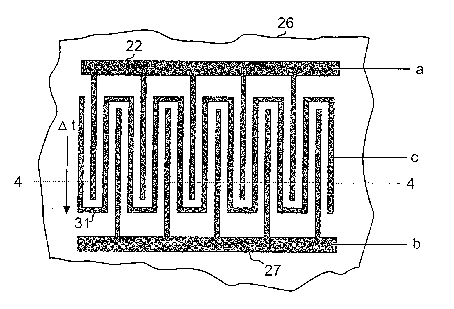
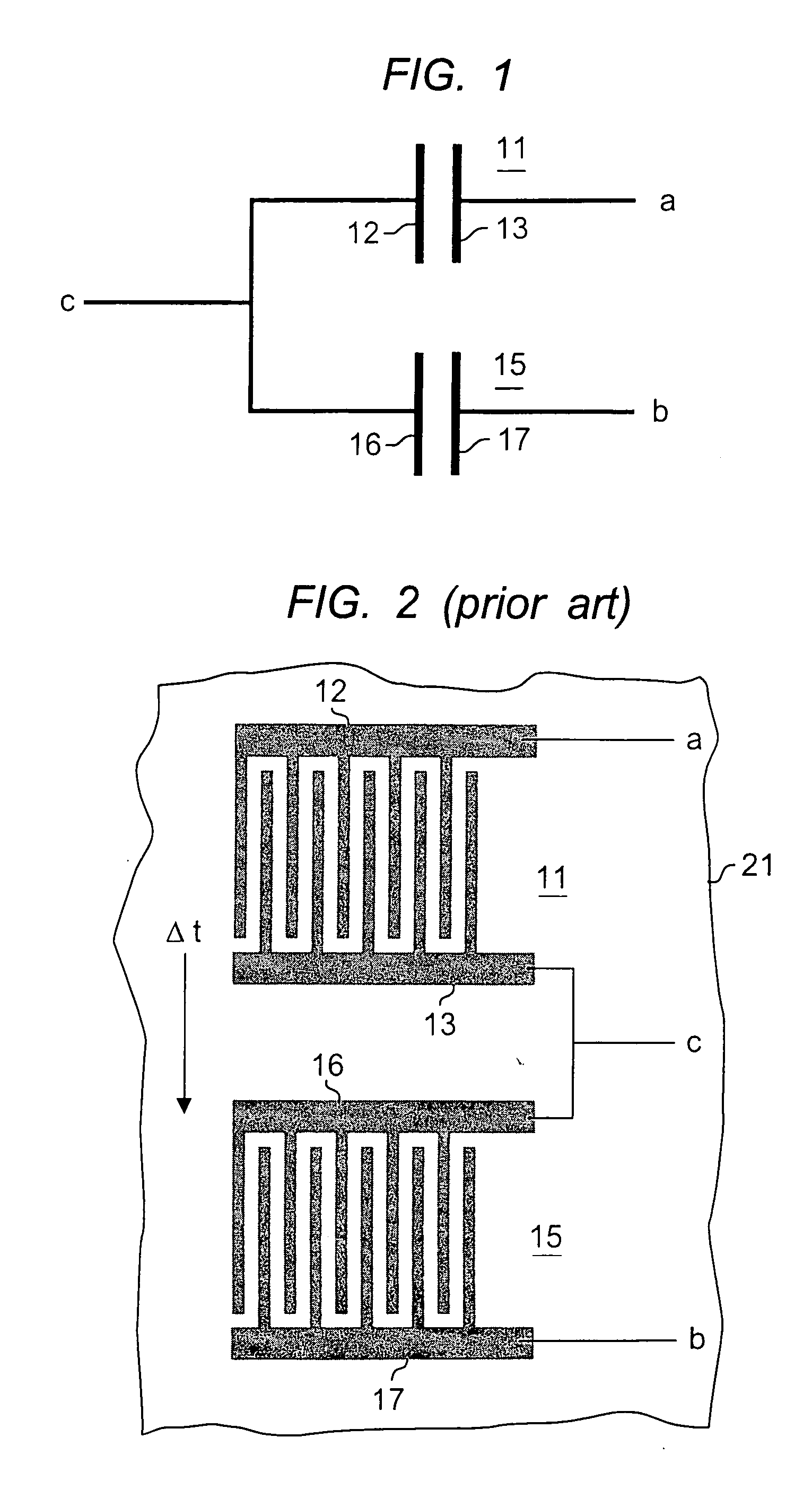
[0013]FIG. 1 shows one circuit embodiment of the invention that will be used for the detailed description. Capacitors 11 and 15 may be connected in the configuration shown, with I / O connections a, b, and c. Capacitor 11 is formed by plates 12 and 13, and capacitor 15 is formed by plates 16 and 17. This capacitor pair is shown implemented using an interdigitated interconnect structure in FIG. 2. Substrate 21 represents any known IC substrate including but not limited to silicon, gallium arsenide, indum phosphide or an IPD substrate such as ceramic. The substrate is shown cut-away indicating that this is a portion, typically a small portion, of a larger substrate or wafer.

[0014] Due to processing variables, it is not uncommon for the thickness of the blanket layer that is patterned to form the discrete interdigitated devices 11 and 15 in FIG. 2 to vary over the surface of the substrate. In IC device manufacture, the substrate is typically a silicon wafer with a plurality of identical...


PUM


Abstract

The specification describes matched capacitor pairs that employ interconnect metal in an interdigitated form, and are made with an area efficient configuration. In addition, structural variations between capacitors in the capacitor pair are minimized to provide optimum matching. According to the invention, the capacitor pairs are interdigitated in a manner that ensures that the plates of each pair occupy common area on the substrate. Structural anomalies due to process conditions are compensated in that a given anomaly affects both capacitors in the same way. Two of the capacitor plates, one in each pair, are formed of comb structures, with the fingers of the combs interdigitated. The other plates are formed using one or more plates interleaved between the interdigitated plates.

Description


Claims


Application Information

Patent Timeline
Owner BELL SEMICON LLC
Why Eureka
Try Eureka