Voltage generating circuit with two resistor ladders

a voltage generation circuit and resistor ladder technology, applied in the direction of electric pulse generator details, pulse technique, instruments, etc., can solve the problems of consuming considerable power, occupying considerable space, and increasing the number of amplifiers proportionally, so as to reduce overshoot and undershoot

Inactive Publication Date: 2006-01-12
LAPIS SEMICON CO LTD
View PDF1 Cites 27 Cited by
  • Summary
  • Abstract
  • Description
  • Claims
  • Application Information

AI Technical Summary

Benefits of technology

[0016] The voltage generating circuit preferably includes a precharging circuit that precharges the output terminals and their connected signal lines to a first potential at the beginning of positive cycles and to a second potential at the beginning of negative cycles, the first potential being higher than the second potential. The first and second potentials may also be supplied to the two ends of each resistor ladder. The first resistor ladder preferably includes a switching element for halting supply of the second potential during negative cycles and during the precharging interval at the beginning of positive cycles. The second resistor ladder preferably includes a switching element for halting supply of the first potential during positive cycles and during the precharging interval at the beginning of ne

Problems solved by technology

A consequent problem is that if the number of source lines is increased to improve the resolution of the display, the number of amplifiers increases proportionally.
For a high-resolution display, the numerous amplifiers take up considerable space and consume considerable power.
A second problem is that each amplifier must be capable of generating the full range of output voltages that might be needed on the source line.
One known solution to this problem is to use rail-to-rail amplifiers of the push-pull type, but this type of amplifier draws substantial current whenever its output changes, exacerbating the power consumption problem.
Another known solution is to use two single-ended amplifiers for each source line, one amplifier operating in the upper half of the output range and the other amplifier operating in the lower half of the output range, and select one amplifier or the other by, for example, comparing the data signal voltage wi

Method used


Image

  • Voltage generating circuit with two resistor ladders
  • Voltage generating circuit with two resistor ladders
  • Voltage generating circuit with two resistor ladders

Examples


first embodiment

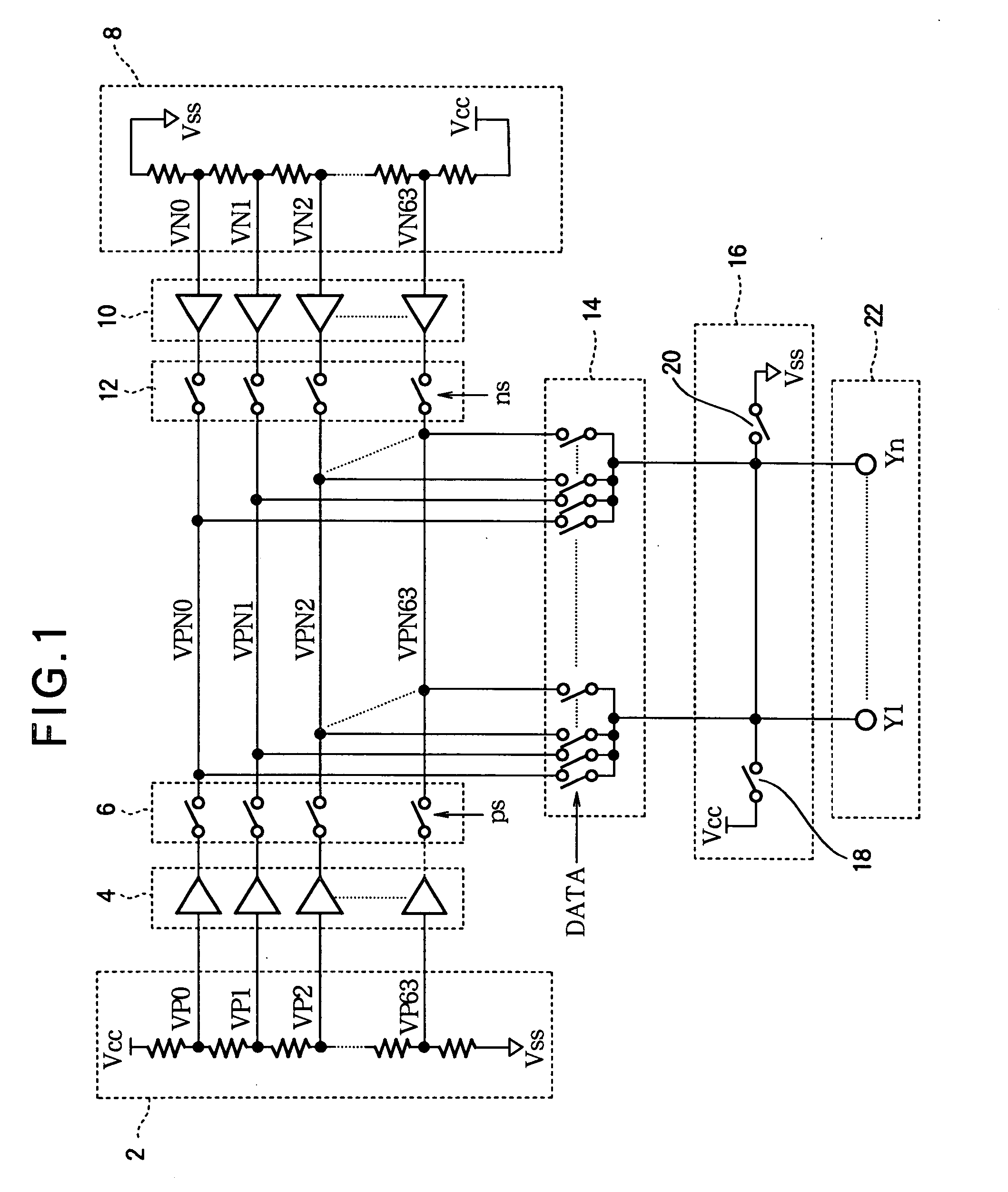
[0035] Referring to FIG. 1, invention is a voltage generating circuit comprising a first resistor ladder 2, a first plurality of amplifiers 4, a first plurality of analog switches 6, a second resistor ladder 8, a second plurality of amplifiers 10, a second plurality of analog switches 12, an output switching circuit 14, a precharging circuit 16 including a pair of switches 18, 20, and a plurality of output terminals 22. In the following description it will be assumed that the output terminals 22, denoted Y1 to Yn, are connected to the source lines of a TFT-LCD panel having a horizontal resolution of n picture elements (pixels), where n is an arbitrary integer greater than one.

[0036] The first resistor ladder 2 receives a first potential Vcc at one end and a second potential Vss at another end, and has sixty-four taps from which voltages VP0 to VP63 intermediate between Vcc and Vss are output. VP0 is relatively close to the Vcc potential, and VP63 is relatively close to the Vss poten...

second embodiment

[0097]FIG. 16 illustrates the general circuit configuration of the invention. This embodiment eliminates the analog switches in FIG. 1 and connects the amplifiers 4, 10 directly to the internal signal lines VPN0-VPN63.

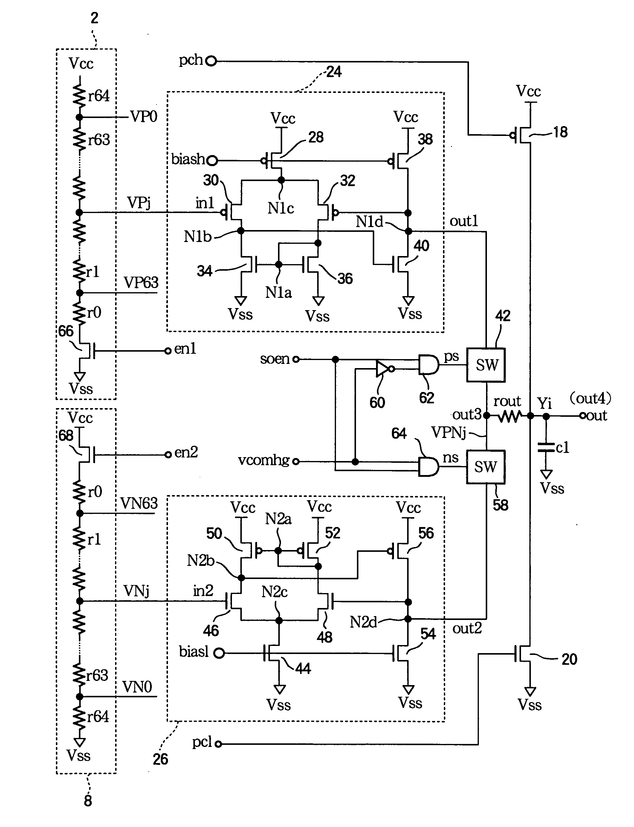
[0098]FIG. 17 illustrates the circuit configuration of the second embodiment in more detail by showing the internal structure of the amplifiers 24, 26 connected to an internal signal line VPNj, where j is an arbitrary integer from 0 to 63. Amplifier 24, which is one of the first plurality of amplifiers 4, combines the features of the first amplifier 24 in FIGS. 12 and 15: that is, it has the basic structure shown in FIG. 2, with additional PMOS transistors 82 and 84 that interrupt current flow during negative driving cycles, and an additional NMOS transistor 76 that turns off NMOS transistor 40 and pulls node N1b down to the Vss level during negative driving cycles. Amplifier 26, which is one of the second plurality of amplifiers 10, similarly combines the features of ...


PUM


Abstract

A voltage generating circuit that drives multiple output terminals in alternating positive and negative cycles has two resistor ladders, one resistor ladder generating voltages for the positive cycles, the other resistor ladder generating voltages for the negative cycles. Single-ended amplifiers are connected directly to the resistor ladders, and a switching circuit connects each output terminal to a selectable one of the amplifiers. The output terminals may be precharged to opposite potentials at the beginning of positive and negative cycles, and the resistor ladders may include switching elements that initially set all generated voltages to these potentials so that the amplifiers start each cycle with equal input and output levels, reducing overshoot and undershoot. This voltage generating circuit saves space and power in driving, for example, a display panel in a mobile telephone.

Description

BACKGROUND OF THE INVENTION [0001] 1. Field of the Invention [0002] The present invention relates to a voltage generating circuit useful for generating voltages required by, for example, a thin-film-transistor liquid crystal display (TFT-LCD) panel. [0003] 2. Description of the Related Art [0004] TFT-LCD panels are used in mobile telephones, to name just one of many applications. The thin-film transistors in a TFT-LCD panel are field-effect transistors through which data signal voltages representing picture element intensity levels or gray levels are applied to capacitors that store charge in proportion to the gray level. The data signal voltages are carried to the source electrodes of the thin-film transistors by source lines (also referred to as data lines) in the TFT-LCD panel. [0005] The data signal voltages are conventionally generated by a resistor ladder and output onto the source lines through a switching circuit that includes a separate voltage-follower amplifier for each s...

Claims


Application Information

Patent Timeline
IPC IPC(8): G05F1/10
CPCG09G3/3614G09G3/3688G09G2330/021G09G2310/027G09G2310/0248
Inventor UTSUNO, KIKUO
Owner LAPIS SEMICON CO LTD
Why Eureka
Try Eureka