
Regulator Circuit with Multiple Supply Voltages

a technology of supply voltage and regulator circuit, which is applied in the direction of electrical equipment, ac network circuit arrangement, instruments, etc., can solve the problems of inaccurate control of output current and output voltage, relatively high construction cost, slow rise and fall times, etc., and achieve accurate output level, save power, and save power

Active Publication Date: 2008-07-10
MICROCHIP TECH INC
View PDF16 Cites 26 Cited by
  • Summary
  • Abstract
  • Description
  • Claims
  • Application Information

AI Technical Summary

Benefits of technology

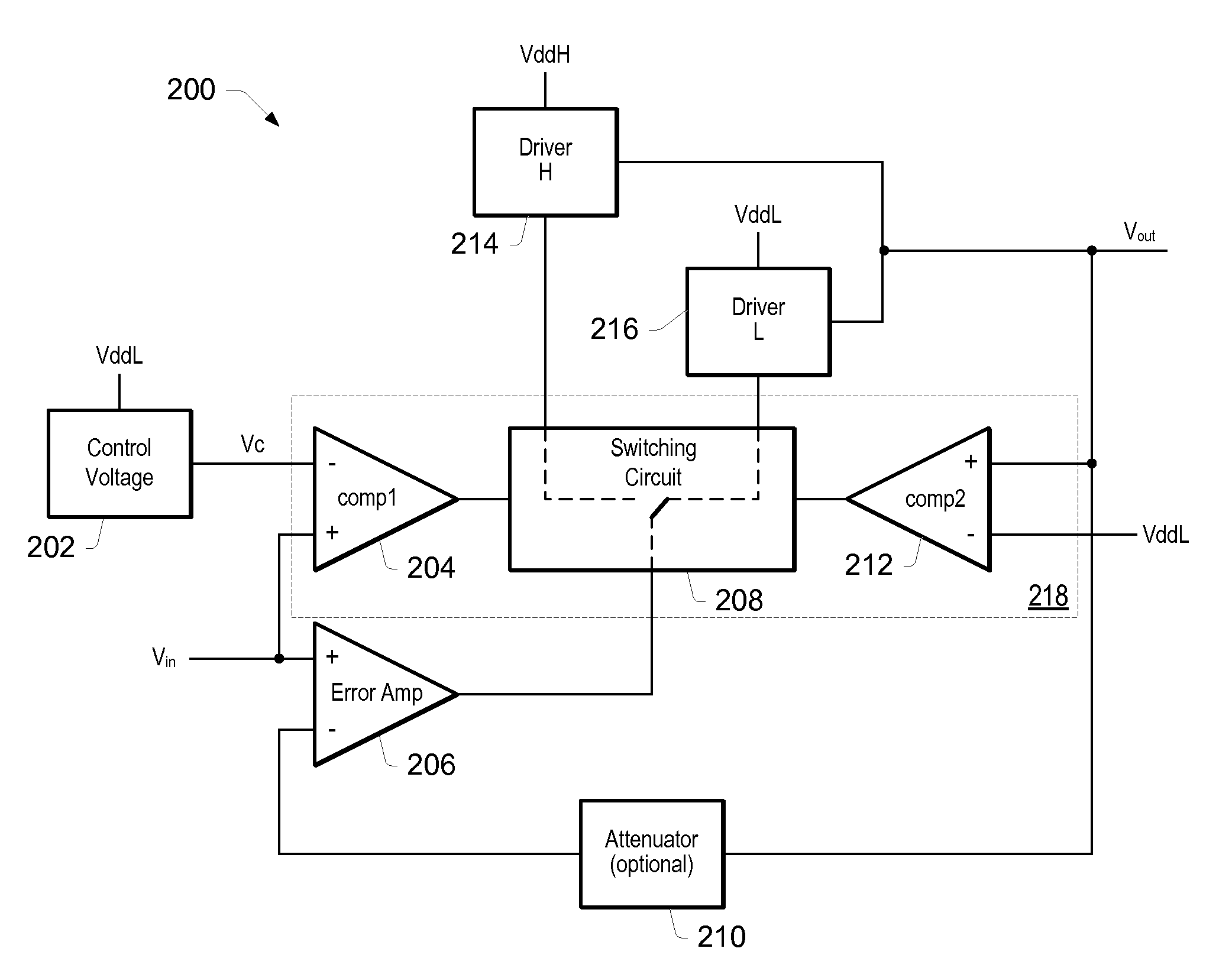
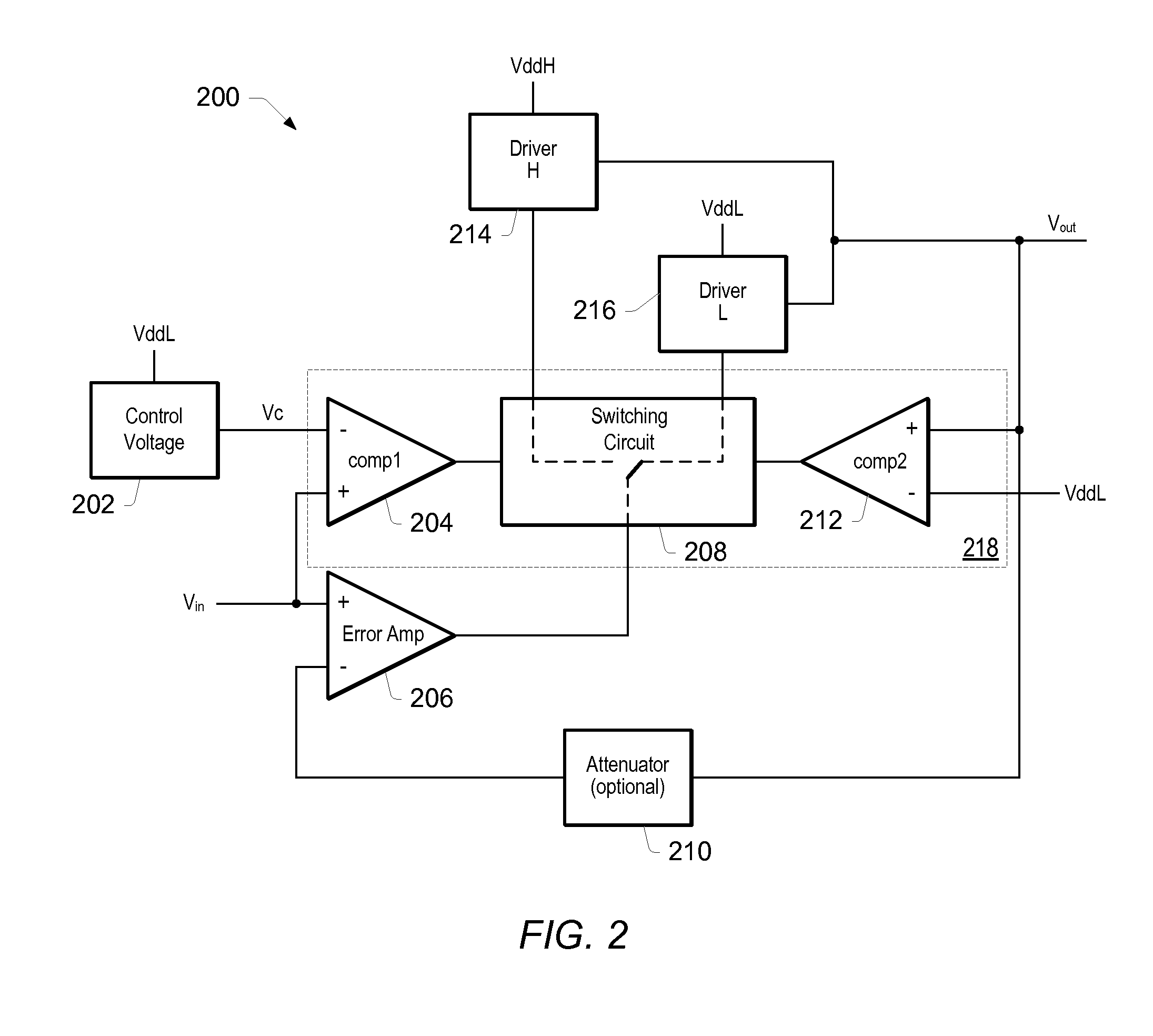
[0013]A voltage regulator (or driver) circuit may be designed with the primary goal to save power. The regulator circuit may be coupled to at least two power supplies configured to provide a supply voltage to the regulator circuit. In order to save power, the regulator circuit may take current from the lowest possible supply according to the value of an input signal, while maintaining an accurate output level.

Problems solved by technology

Typically, these driver circuits may be relatively expensive to build.
Other driver circuits may feature simple or simpler designs, failing, however, to accurately control output currents and output voltages, while also having slow rise and fall times.
While this provides effective protection, it also places a limit on the efficiency of the contribution provided by the lower voltage power supplies to the overall amplifier output.
Some power will unavoidably be dissipated in the diode as a result of the voltage drop across the diode, any time a lower voltage supply is contributing to the overall output of the amplifier.
This power would be wasted any time the supply contributed to the amplifier output.
While such a voltage drop and corresponding inefficiency may be acceptable in relatively high voltage amplifiers where the output is in the 10V range (typically tens of volts), integrated circuit amplifiers for low-power applications are typically designed to operate with minimum supply voltages below two volts, and such a drop in output stage voltage would limit the amplifier's maximum efficiency to less than fifty percent.
Certain drawbacks of this solution are apparent, however.
For example, current may flow from a high supply to low supply during fast signal transients, causing extra power dissipation.
This may occur due to the pass devices to the two supplies conducting simultaneously, in addition to the slow speed of the control loop.
Another issue may be the less than optimal power saving due to a transition region from one supply to the next supply having a value in the 100 mV range (typically hundreds of mV).
Finally, the feedback loop can be very difficult to stabilize.

Method used


Image

  • Regulator Circuit with Multiple Supply Voltages
  • Regulator Circuit with Multiple Supply Voltages
  • Regulator Circuit with Multiple Supply Voltages

Examples


Embodiment Construction

[0026]As used herein, the “magnitude” of a power supply refers to the magnitude of the supply signal provided by the power supply. For example, the magnitude of a voltage supply refers to the magnitude of the voltage signal provided by the voltage supply. E.g. a voltage supply having a magnitude of 5V indicates that the voltage supply is configured to provide a 5V supply rail and / or supply voltage. As also used herein, a “ratio” of a current mirror device refers to a ratio between the current conducted by the input branch of the current mirror and the current conducted by the output, or mirror branch of the current mirror. Thus, a current mirror having a “very high” ratio may indicate that the ratio of the input current vs. the mirrored current is approximately 1:1000. Furthermore, the “size” of a transistor or transistor device may refer to the channel width to channel length ratio of the transistor device. Thus, a “large” transistor may have a channel width to channel length ratio...


PUM


Abstract

A regulator circuit may be configured to operate with multiple power supplies. The regulator circuit may be configured to receive an input voltage and provide a regulated output voltage at an output terminal as a function of the input voltage. The regulator may include at least two drivers. A first driver may have a driver output coupled to the output terminal and have a supply terminal coupled to a high power supply, and a second driver may have a driver output coupled to the output terminal and have a supply terminal coupled to a low power supply. A selector circuit may be configured to compare the input voltage with a control voltage that has a magnitude just below a magnitude of the low power supply, to determine which driver to select from the first driver and the second driver, and enable either the first driver output or the second driver output to be active according to which driver has been selected. The regulator circuit may be configured to operate with any number of power supplies by including corresponding drivers and selection logic in the selector circuit.

Description

BACKGROUND OF THE INVENTION[0001]1. Field of the Invention[0002]This invention relates generally to voltage / current driver / regulator circuit design and, more particularly, to the design of a regulator circuit operating with multiple supply voltages.[0003]2. Description of the Related Art[0004]A variety of driver circuits exist today for use in integrated circuits and systems for driving a signal line or a bus. Oftentimes driver circuits are configured to enable bus transactions between a source device and a target device, and feature complex designs in order to meet various system specifications. Typically, these driver circuits may be relatively expensive to build. Other driver circuits may feature simple or simpler designs, failing, however, to accurately control output currents and output voltages, while also having slow rise and fall times.[0005]One variety of driver circuits generally comprises a relatively low power circuit that drives, or controls, a higher power device, whic...

Claims


Application Information

Patent Timeline
Patent Type & Authority Applications(United States)
IPC IPC(8): H02J3/00
CPCG05F1/56
Inventor ILLEGEMS, PAUL F.
Owner MICROCHIP TECH INC
Learn More