Method and device for tracking the directions-of-arrival of radio waves

a radio wave and direction-of-arrival technology, applied in direction finders using radio waves, multi-channel direction-finding systems using radio waves, instruments, etc., can solve problems such as the performance degradation of the receive and transmission systems of the base station, and achieve the effect of reducing the computational load

Inactive Publication Date: 2006-01-12
FUJITSU LTD
View PDF3 Cites 36 Cited by
  • Summary
  • Abstract
  • Description
  • Claims
  • Application Information

AI Technical Summary

Benefits of technology

[0021] According to the first aspect, the arrival directions of incident signals be estimated in a new way by exploiting the cyclostati...

Problems solved by technology

Furthermore when the direction of the desired signal is varying over time, the conventional method cannot estimate the directions at quickly and accurately, and hence a re...

Method used


Image

  • Method and device for tracking the directions-of-arrival of radio waves
  • Method and device for tracking the directions-of-arrival of radio waves
  • Method and device for tracking the directions-of-arrival of radio waves

Examples


first embodiment (

(A) First Embodiment (Constant Directions)

[0038] The first embodiment is a method and device for estimating the constant directions of coherent cyclostationary signals accurately and the first embodiment will be described with reference to the drawings. In the following drawings, composing elements which are roughly identical or have the same function are denoted with a same reference symbol.

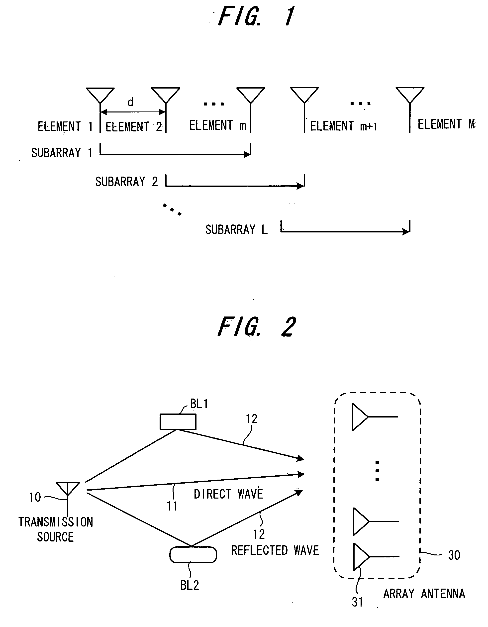
[0039]FIG. 1 is a diagram depicting an array antenna, where M antenna elements are linearly placed with the adjacent spacing of d. FIG. 2 is a diagram depicting the the transmission source 10 and the array antenna 30 at the base station. The array antenna 30 has the same configuration as that shown in FIG. 1 and constitutes the direction estimation system. In FIG. 2, the direct wave 11 impinges straightly from the transmission source 10 on the array antenna 30, and the reflected wave 12 impinges the array antenna 30 after being reflected by the buildings BL1 and BL2. In FIG. 2, two reflected wa...

second embodiment

(B) Second Embodiment

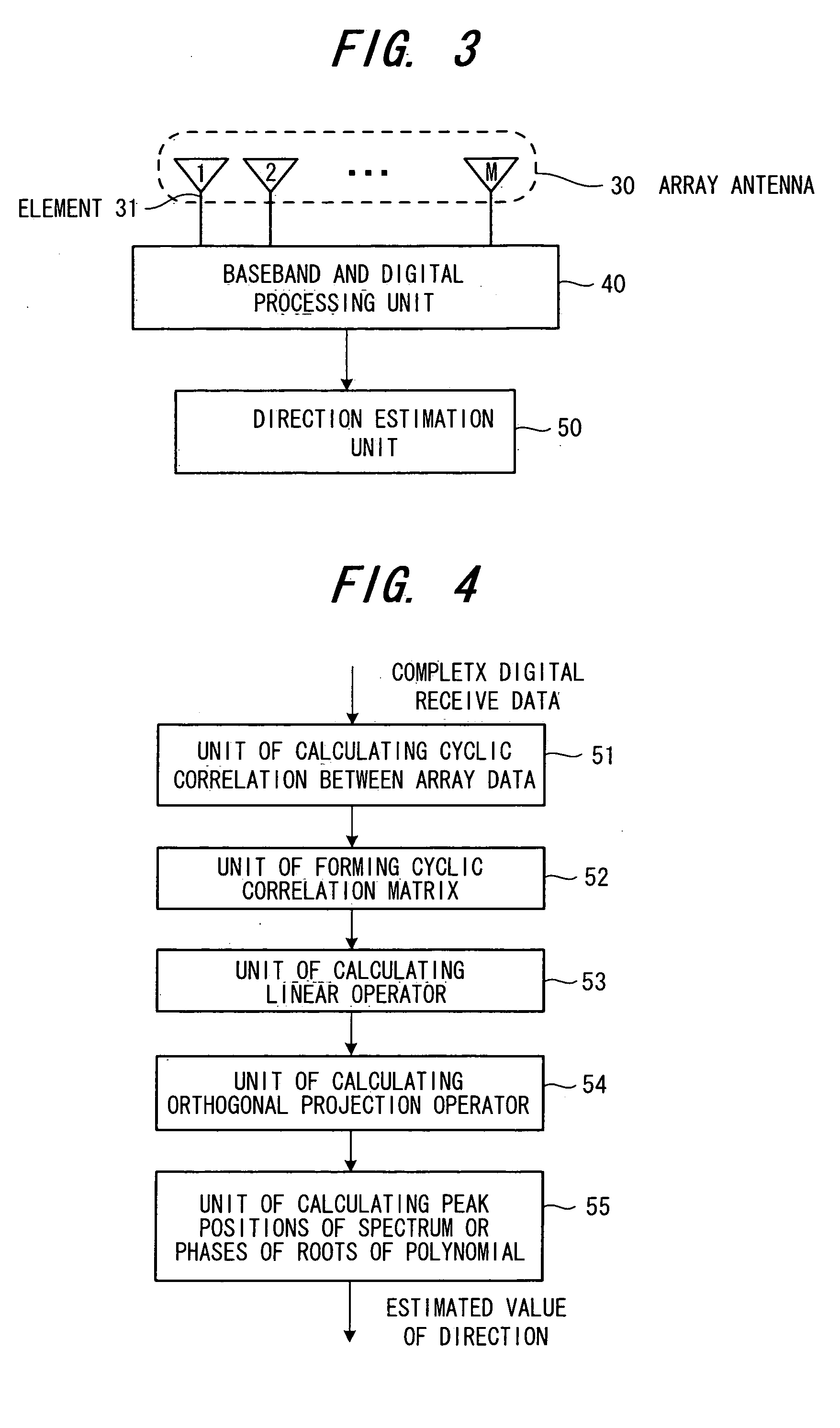
[0059] The direction estimation unit 50 of the first embodiment (FIG. 3) can estimate the directions of the cyclostationary signal without eigendecomposition. The first embodiment, however, can be applied only when the directions of incident signals are constant. If the direction of an incident signal varies over time, the estimation method of the first embodiment should be modified as an online algorithm so that the time-varying direction can be accurately estimated.

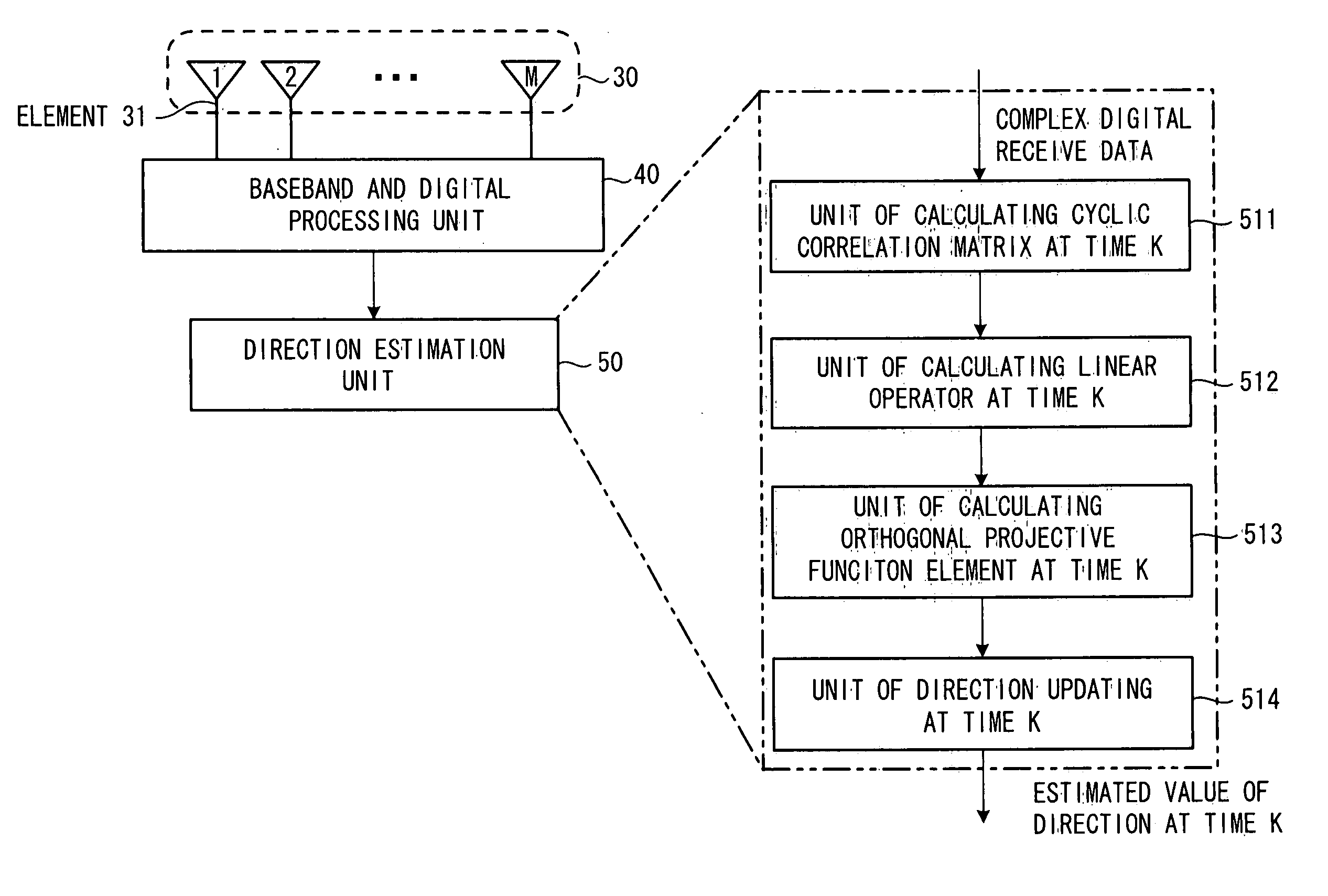
[0060]FIG. 8 is a diagram depicting the configuration of the direction estimation unit 50 when the direction of the incident signal varies over time. Now the procedure for tracking the directions of the cyclostationary signals will be described.

[0061] First the unit 511 of calculating the cyclic correlation matrix at time K recursively calculates the cyclic correlation matrices Ψf (K, τ) and Ψb (K, τ) at time K by the following expressions

Ψf(K,τ)=μΨf(K−1,τ)+Xf(K−τ)xM*(K)e−j2xα(K−τ)  (19a)

Ψb(K,τ)...

third embodiment

(C) Third Embodiment

[0074] Receiver at Base Station

[0075] A base station receiver can be constructed by a device for estimating the direction of cyclostationary signals and beamforming means for forming the receiving beam-pattern so that its peak turns towards the estimated directions obtained by the device for estimating the direction.

[0076]FIG. 11 is a diagram depicting the configuration of this receiver of base station. The array antenna 30 receives signals and inputs them into the baseband and digital processing unit 40. The digital processing unit 40 processes the signals for each antenna element and outputs the complex digital received data. The direction estimation unit 50 estimates the directions of the coherent signals by using the received array data. The beamforming unit (receiving beamformer) 60 forms a beam, where the beam peak is in the estimated direction obtained by the direction estimation unit 50. In other words, the beamforming unit 60 extracts the desired signa...


PUM


Abstract

L overlapping forward subarrays with {overscore (q)} (≧q) antenna elements are formed with, where q is the number of desired signals, a cyclic correlation matrix is formed from the cyclic correlations between the received signals of L forward subarrays and a received signal of the first predetermined antenna element, the cyclic correlated matrix is divided into two upper and lower submatrices, an orthogonal projection operator in the noise subspace is calculated by performing a linear operation on these two upper and lower cyclic correlation matrices, then by calculating a spatial spectrum or a polynomial by using the estimated orthogonal projection operator, the directions are estimated from of the position of q highest peaks of the spatial spectrum or the phases of q roots of the polynomial closest to the unit circle in z-plane.

Description

BACKGROUND OF THE INVENTION [0001] This invention relates to a method and device for estimating the directions-of-arrival (DOAs) of the radio waves impining on the array antenna at a base station, where the directions of the incoming radio waves can be accurately estimated. More particularly, it relates to a method and device for estimating the DOAs of the radio waves with cyclostationarity without the need of the complicated eigendecomposition and can tracking the time-varying directions accurately and quickly. [0002] Research and development on the applications of an adaptive array antenna for mobile communication is currently gathering attention, where multiple antenna elements are placed in different spatial positions with predetermined geometry. The estimation of the directions of the radio waves (hereafter the radio waves may be called “signals” from the signal processing point of view) impinging on the array antenna is one of the important fundamental technich for the adaptiv...

Claims


Application Information

Patent Timeline
IPC IPC(8): G01S5/02G01S3/46G01S3/74G06K9/00H04B7/08
CPCG01S3/46H04B7/086G06K9/0057G01S3/74G06F2218/22
Inventor XIN, JINGMIN
Owner FUJITSU LTD
Why Eureka
Try Eureka