
Integrated artificial and natural lighting system

Active Publication Date: 2006-01-12
SUNPORT IND
View PDF8 Cites 45 Cited by
  • Summary
  • Abstract
  • Description
  • Claims
  • Application Information

AI Technical Summary

Benefits of technology

[0012] It is an advantage of the present invention that it reduces heat build up in the light shaft and heat transfer into the building.
[0013] It is another advantage of the present invention that it is easily retrofitted into existing skylights in buildings.
[0014] It is another advantage of the present invention that excess heat may be utilized to heat hot water for use in the building.
[0015] It is a feature of the present invention that photovoltaic cells are used as an energy source.
[0016] It is a further feature of the present invention that relatively high powered color rendition index light emitting diode sources are used.
[0017] It is yet another feature of the present invention that a freznel lens is used to direct light onto the solar or photovoltaic cells.

Problems solved by technology

While most skylights incorporating lamps or artificial lighting extend the practicality of skylights and their use for providing light when natural light is not available, they are often difficult to retrofit and require external power to energize the lamps or artificial lighting.
The need to connect to an external power source makes the installation more complicated and may limit design flexibility.

Method used


Image

  • Integrated artificial and natural lighting system
  • Integrated artificial and natural lighting system
  • Integrated artificial and natural lighting system

Examples


Embodiment Construction

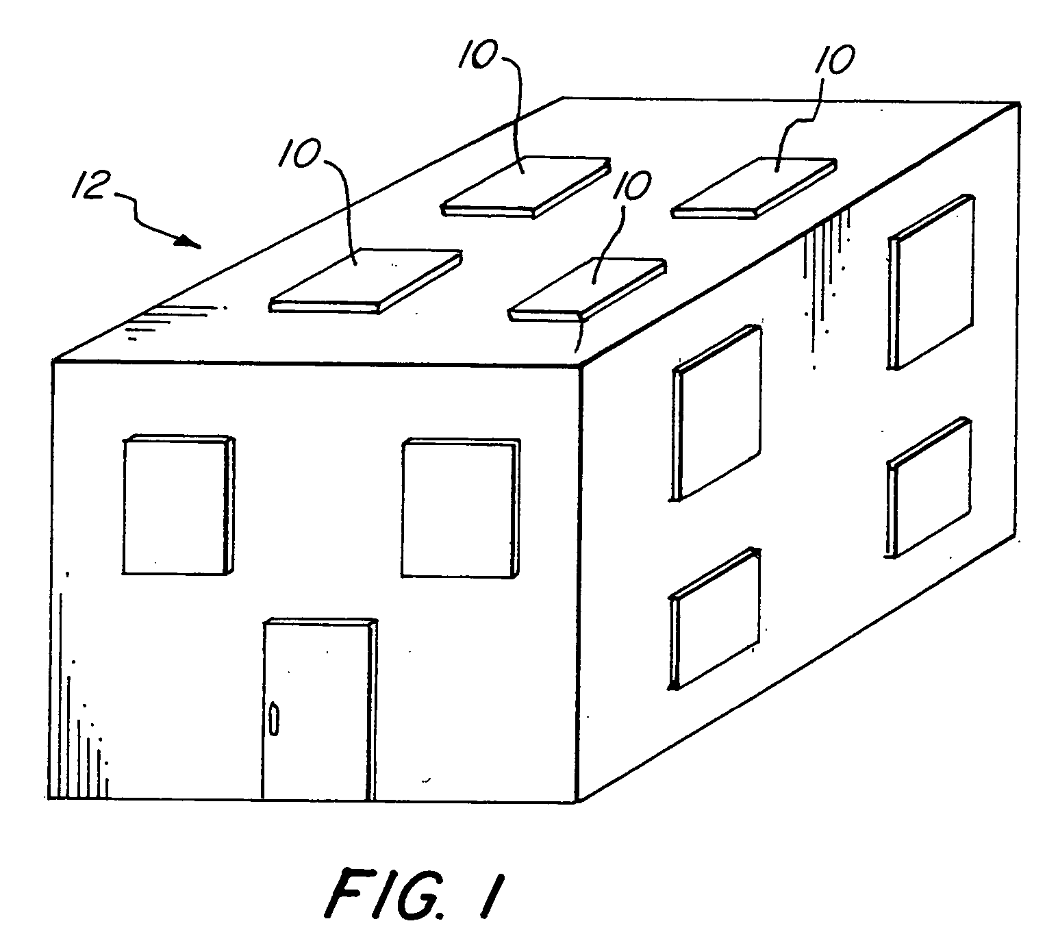
[0025]FIG. 1 illustrates schematically a building 12 having a plurality of skylights, sky windows, illumination units, or combined natural and artificial lighting systems 10 installed. The illumination unit or lighting system 10 of the present invention is applicable to both commercial and residential applications.

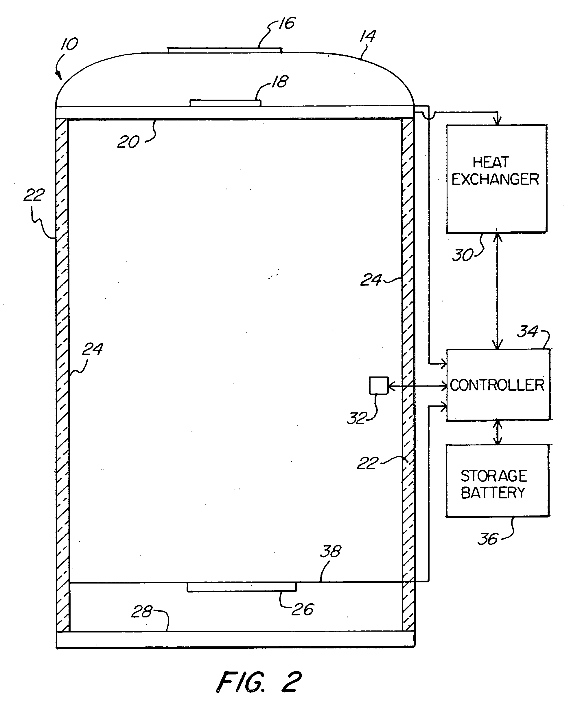
[0026]FIG. 2 schematically illustrates one embodiment of the lighting system of the present invention. Illumination unit or lighting system 10 has a top diffuser 14. Placed on the top diffuser 14 is a lens 16. Lens 16 is preferably a Fresnel lens. The lens 16 concentrates natural light onto a photovoltaic or solar cell 18. Preferably the lens 16 adjacent the diffuser 14 has a surface area or size that is relatively small compared to the surface area or size of the diffuser 14. Preferably, the surface area of the lens 16 is less than ten percent of the surface area of the diffuser 14. This permits sufficient natural light to be used for illumination. However, due to the fo...


PUM


Abstract

An artificial and natural lighting system placed in the roof of a building that is substantially self-contained and powered. A photovoltaic cell provides electricity stored in a battery to power light emitting diodes. A highly reflective interior coating applied to the light shaft maximizes lighting intensity. A sensor detects illumination intensity and temperature within the light shaft to control the balance of natural and artificial light provided to maintain predetermined illumination intensity. The light shaft is insulated to reduce heat transfer and a thermal collector removes heat from the building. In one embodiment, a Fresnel lens is utilized to focus natural light onto the photovoltaic cell. In another embodiment, conventional fluorescent lighting powered by external line voltage is combined with light emitting diodes powered primarily by a rechargeable battery. The present invention, being substantially self-contained, is easily retrofitted to existing buildings with a minimum of connections and provides substantial energy efficiencies in illuminating the building.

Description

RELATED APPLICATION [0001] This application claims the benefit of U.S. Provisional Application No. 60 / 514,943, filed Oct. 28, 2003.FIELD OF THE INVENTION [0002] The present invention relates in general to a sky window or skylight for providing natural and artificial light into a building, and more particularly to a highly efficient self-contained lighting system capable of being independent of external power sources. BACKGROUND OF THE INVENTION [0003] Skylights or sky windows have often been used to illuminate the interior of buildings. Most skylights are passive devices that act as windows relying completely on natural daylight for illuminations. Some skylights have combined the benefits of natural lighting with artificial lighting. One such skylight is disclosed in U.S. Pat. No. 5,528,471 entitled “Skylight And Lamp Combination” issuing to Green on Jun. 18, 1996. Therein disclosed is a skylight and lamp combination for providing natural and artificial light to a room. A plurality ...

Claims


Application Information

Patent Timeline
IPC IPC(8): G02B17/00
CPCE04D13/033E04D2013/0345F21S9/037F21S11/00F21S19/005Y10S385/90F21Y2101/02F21Y2103/00F21Y2113/00F21Y2113/02Y10S362/80F21V29/004F21Y2113/20F21Y2103/10F21Y2115/10F21V29/15
Inventor ZINCONE, ROBERT
Owner SUNPORT IND
Learn More