
Blender with cooling/muffling functions

a technology of muffler and function, which is applied in the field of blenders, can solve the problems of reducing airflow, adversely affecting the cooling effect of the motor, so as to achieve the effect of improving the heat dissipation

Inactive Publication Date: 2006-01-12
LEE PAO CHEN +1
View PDF8 Cites 55 Cited by
  • Summary
  • Abstract
  • Description
  • Claims
  • Application Information

AI Technical Summary

Benefits of technology

[0006] An object of the present invention is to provide a blender with an improved heat-dissipating effect.
[0007] Another object of the present invention is to provide a blender with an improved muffling effect.
[0008] A further object of the present invention is to provide a blender with improved safety and improved air-guiding efficiency.
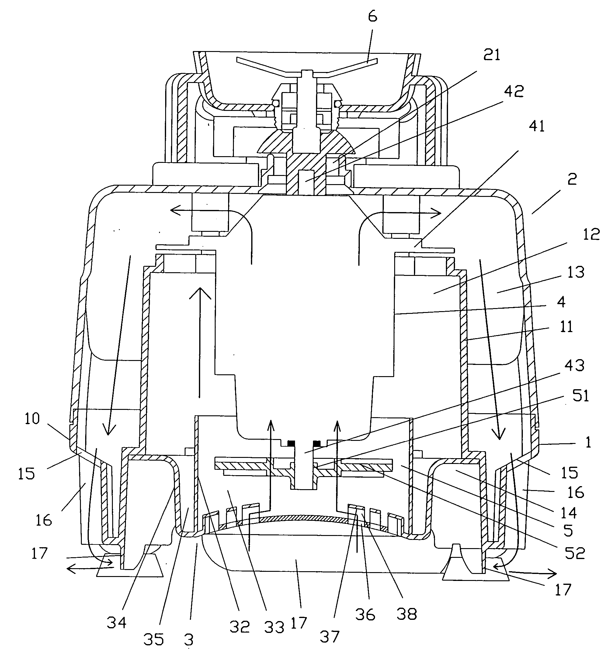
[0010] The muffler housing is mounted to the bottom end of the base frame and includes a plurality of apertures communicated with the opening of the base frame for guiding air. The motor is received in the compartment of the hollow column. The motor includes an upper drive shaft for driving a mixing blade means and a lower drive shaft for driving the fan for driving ambient cool air into the compartment of the hollow column via the notch, the air-guiding groove, the apertures, thereby directly cooling the motor, with hot air exiting the blender after passing through the compartment, the space, the slots, and the recessed portions of the base frame, and with the separating plates preventing the hot air from entering the blender.

Problems solved by technology

The cooling effect of the motor 4′ is thus adversely affected.
Further, the travel for the ambient airflow to the motor 4′ is relatively long and thus adversely affects the cooling effect for the motor 4′, as the velocity of the airflow is reduced.

Method used


Image

  • Blender with cooling/muffling functions
  • Blender with cooling/muffling functions
  • Blender with cooling/muffling functions

Examples


Embodiment Construction

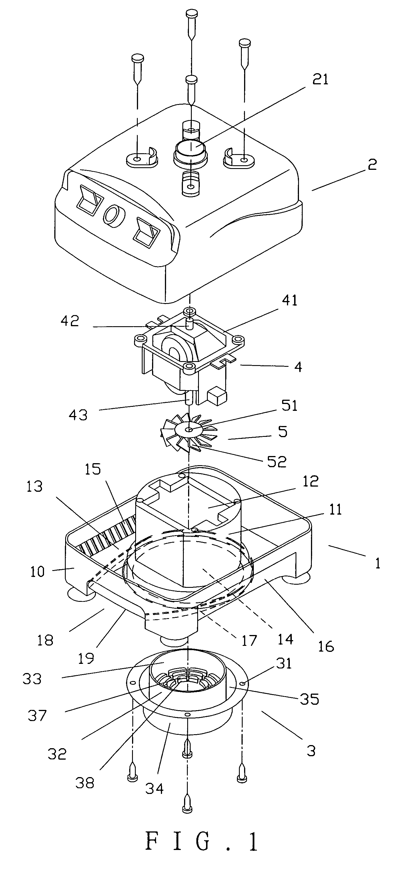
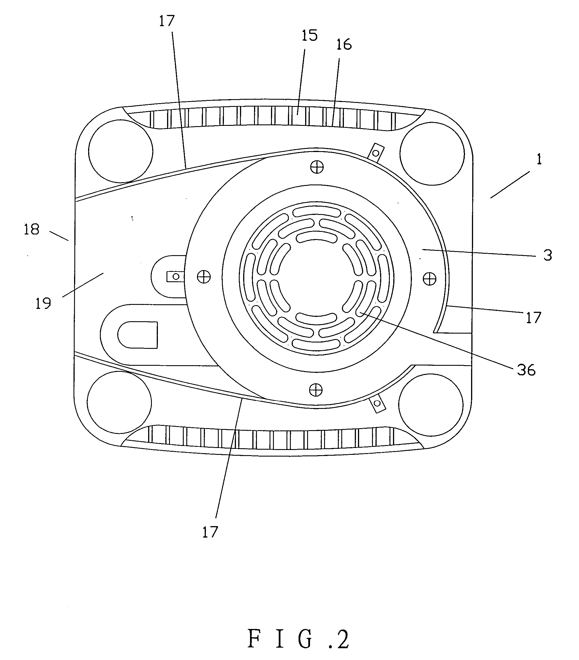
[0019] Referring to FIGS. 1 through 3, a blender in accordance with the present invention comprises a base frame 1, a cover 2, a muffler housing 3, a motor 4, and a fan 5. The base frame 1 includes a hollow column 11 in a central portion thereof, defining a compartment 12 for receiving the motor 4. The base frame 1 further includes a perimeter wall 10 surrounding the hollow column 11, defining a space 13 between the perimeter wall 10 and the hollow column 11 for receiving a circuit board (not labeled). The base frame 1 further includes an opening 14 in a bottom end thereof. Further, the perimeter wall 10 of the base frame 1 includes slots 15 in two opposite sides thereof, with each of the opposite sides including a recessed portion 16 for guiding air. Two separating plates 17 extend downward from the bottom end of the base frame 1 and face the opposite sides, respectively. A notch 18 is defined in the perimeter wall 10 and not aligned with the slots 15, with an air-guiding groove 19...


PUM


Abstract

A blender includes a base frame, a cover for covering the base frame, a muffler housing, a motor, and a fan. The base frame includes a hollow column having a compartment for receiving the motor. Two separating plates extend downward from a bottom end of the base frame. The motor includes a lower drive shaft for driving the fan for driving ambient cool air into the compartment of the hollow column via the apertures, thereby directly cooling the motor. The separating plates prevent the hot air exiting the blender from entering the blender again.

Description

BACKGROUND OF THE INVENTION [0001] 1. Field of the Invention [0002] The present invention relates to a blender. In particular, the present invention relates to a blender with cooling / muffling functions. [0003] 2. Description of the Related Art [0004] U.S. Pat. No. 5,273,358 discloses a quiet and efficient motor cooling fan assembly for a blender. As illustrated in FIG. 5 of the drawings, the blender includes a base frame 1′, a cover 2′, a muffler housing 3′, a motor 4′, and a fan 5′. The base frame 1′ is hollow and includes a compartment 11′ in an upper central portion thereof for receiving the motor 4′ and a plurality of apertures 12′ for air intake. The cover 2′ is mounted on top of the base frame 1′ and includes a bottom engaged with the base frame 1′. Mounted below a central portion of the base frame 1′ is the muffler housing 3′ for receiving the fan 5′. The muffler housing 3′ includes exit apertures 31′. The motor 4′ fixed in the compartment 11′ includes an upper drive shaft 41...

Claims


Application Information

Patent Timeline
Patent Type & Authority Applications(United States)
IPC IPC(8): B01F7/00B01F7/16H02K7/14H02K9/06H02K9/14
CPCH02K7/14H02K9/14H02K9/06A47J43/0716
Inventor TAI, CHUN-YU
Owner LEE PAO CHEN
Learn More