Optical disc recording method and optical disc drive

a recording method and optical disc technology, applied in the field of optical disc recording methods and optical disc drives, can solve the problems of not evaluating the reliable recording must continue without evaluating the sufficient recording quality of recorded data, and reducing the laser output change, good recording quality

Inactive Publication Date: 2006-01-12
HITACHI CONSUMER ELECTRONICS CORP
View PDF10 Cites 2 Cited by
  • Summary
  • Abstract
  • Description
  • Claims
  • Application Information

AI Technical Summary

Benefits of technology

[0016] Accordingly, the present invention evaluates the recording quality of data recorded at a moderate time in course of recording and reflects the result in the laser output. A conventional disc drive records a series of data continuously as specified in a standard, whereas the present invention splits a series of data to be recorded and makes a recording intermittently in a unit of split data. As a result, control is performed so that a series of data recorded can be produced in the same manner as when data was recorded continuously. Subsequently, control is performed so that the recording quality can be maintained satisfactorily over a series of the whole data to be recorded by reflecting the result in the laser output of the next data recording based on the recording state of the data reproduced by reproducing the data that was recorded before each data that was split using a duration obtained by the intermittent recording is recorded. Further, control is performed so that good recording quality can be maintained even in the recording lasting for a long time by stopping the function of each part inside a disc drive within the duration or disconnecting the power to suppress the temperature rise inside the disc drive and thereby decreasing a laser output change. Moreover, a series of data in which recording data is data to be recorded continuously in a standard is split and recording is made intermittently in the split unit.

Problems solved by technology

However, in the recording method as specified in the standard, a problem occurred in some cases according to the type of the disc, the shape of the drive, or the data recorded in the disc.
Usually, the sensitivity of a disc to laser beam is not uniform over the whole disc surface.
Accordingly, in this recording method, recording must be continued without evaluating the sufficient recording quality of recorded data until all data is recorded.
Accordingly, because a conventional optical disc drive cannot interrupt the recording in the recording method, such as above Disc at Once, reliable recording quality is not evaluated.
Accordingly, it was difficult to maintain appropriate recording quality concerning the whole data that was recorded.
When the size of a series of data to be recorded is large and continuous recording lasts for a long time in particular, sufficient recording quality cannot be evaluated in course of recording.
Accordingly, the laser output cannot be controlled appropriately and there was a problem of the deterioration or unevenness of recording quality.
Further, because the temperature inside a disc drive becomes extremely high due to continuous recording, laser cannot be used under good temperature characteristics.
Accordingly, the maintenance of the recording quality was difficult.
Further, the maintenance of the recording quality was difficult in a compact disc drive of which the mounting of a cooling means, such as a fan, also causes a cost increase and that has no room for space and is limited in a power supply.
Accordingly, it was difficult to make a recording in a good recording condition after the recording quality is checked sufficiently during that time.
This was a problem when real time data, such as a video and an audio, is recorded in particular.
That is, after all data have been recorded, it impossible to evaluate recording quality evaluated, and to redo the recording from the beginning if the recording quality is bad.
Because of such reason, the conventional disc drive could not take corrective action for real time recording sufficiently.
Further, even in the case of non-real time recording that enables undoing of recording, the time for undoing the recording occurs.
In a medium, such as a DVD-R, in which a disc enables recording only once, a new disc had to be prepared and even costs was wasted.
As described above, when a series of data, such as Disc at Once recording, must be recorded continuously in particular, such Disc at Once recording, it was difficult for a conventional disc drive to satisfactorily maintain the recording quality of the whole recorded data.
Further, accordingly, the real time recording of a video and an audio in which the recording data itself becomes an original source at once is not suitable for a recording method, such as the Disc at Once recording, in which a series of data must be recorded continuously.
The recording of real time data into a disc, such as a DVD-R in particular, in which recording is enabled only once was difficult.

Method used


Image

  • Optical disc recording method and optical disc drive
  • Optical disc recording method and optical disc drive
  • Optical disc recording method and optical disc drive

Examples


Embodiment Construction

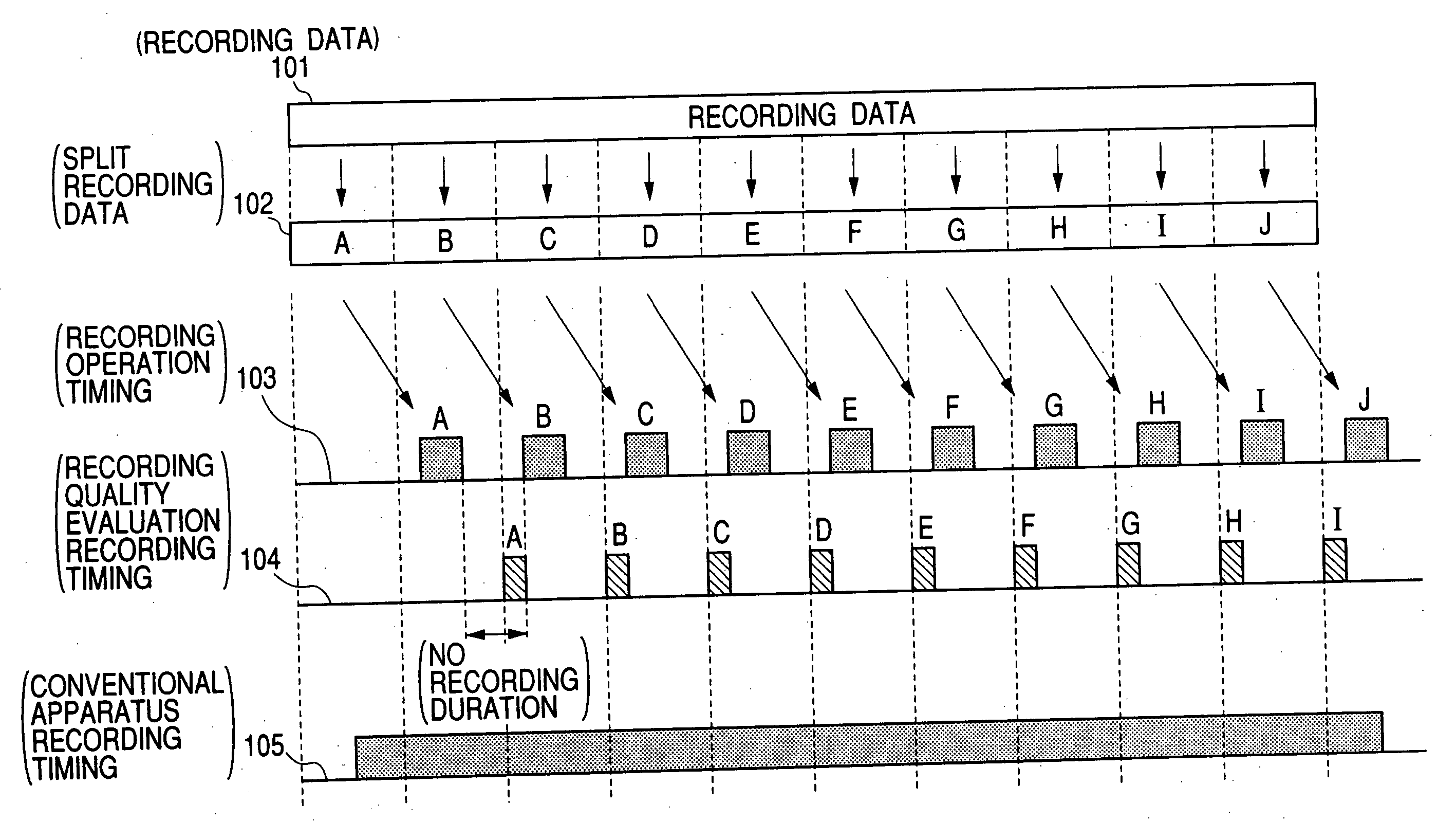
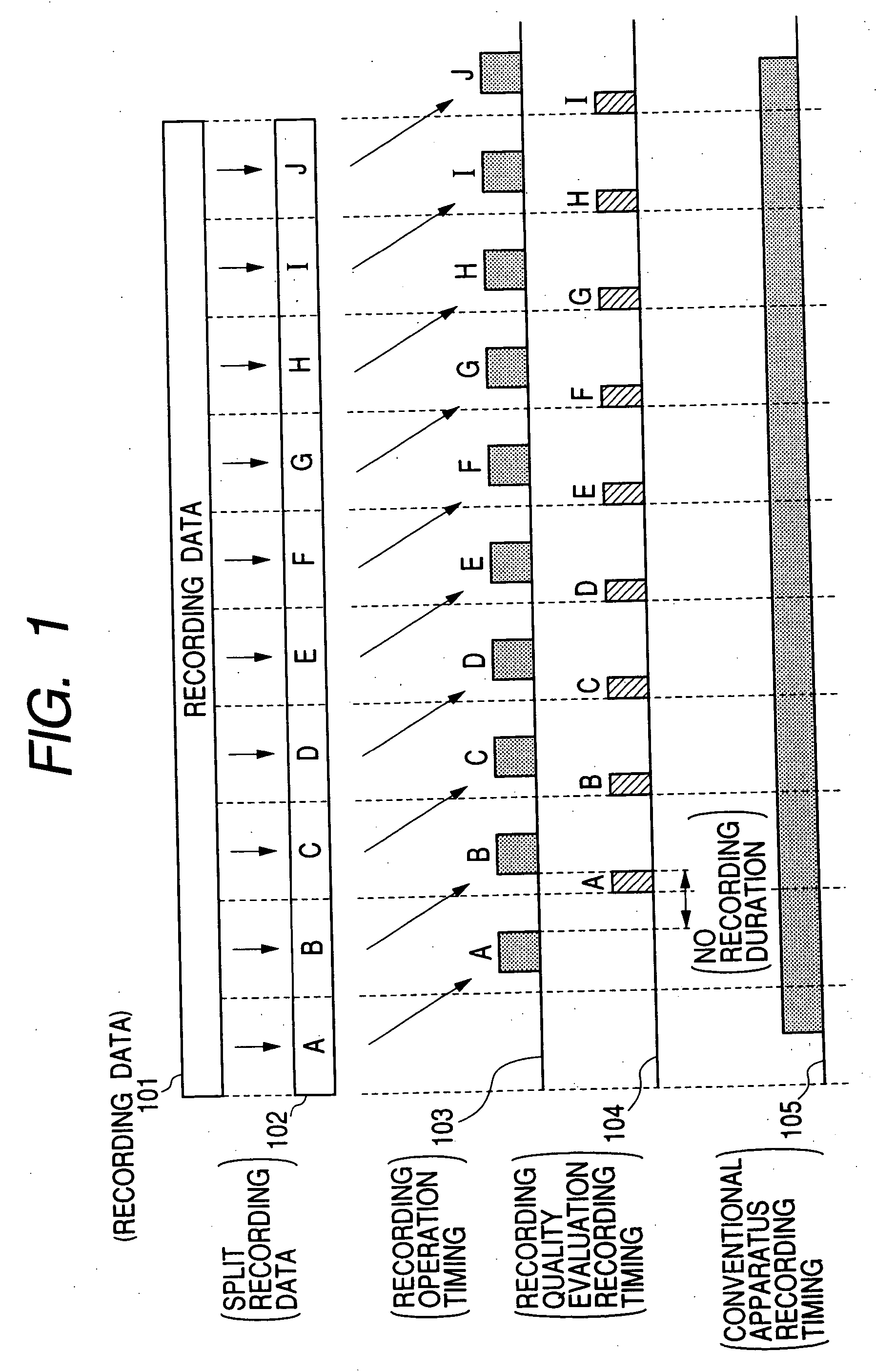
[0022] An embodiment of a data recording method for an optical disc of the present invention is shown in FIG. 1.

[0023] In FIG. 1, 101 are a series of recording data to be recorded continuously in a standard. For comparison, 105 show the recording timing of a conventional disc drive. In the conventional disc drive, as shown in 105, when a part of the data to be recorded in the disc drive is accumulated, the sequentially accumulated data is recorded continuously without interrupting recording halfway.

[0024] On the other hand, in this embodiment, as shown in 102, the recording data 101 is split and managed in a fixed recording unit. For example, in a DVD-R, the data is split in a unit multiplied by an integer of an ECC block unit and recorded. In FIG. 1, the data is split into ten of A to J as an example. The split recording data 102 of the A to J that was split is split and recorded intermittently at the timing shown in 103. The reason why the recording period of each split data bec...


PUM

PropertyMeasurementUnit
temperatureaaaaaaaaaa
poweraaaaaaaaaa
timeaaaaaaaaaa

Abstract

Because a series of data is recorded continuously, the recording quality of data recorded in course of recording cannot be evaluated. Accordingly, the laser output cannot be controlled properly and there are a deterioration and dispersion of the recording quality. Further, when the recording lasts for a long time, the temperature in the vicinity of laser rises due to the heat from the inside of a disc drive and the recording quality is deteriorated. To solve this, a series of data to be recorded is split and recording is made intermittently in a split data unit. The recording quality is evaluated by reproducing the data recorded nearby before each split data is recorded using a duration and control is performed by reflecting the evaluation result in the laser output so that the recording quality can be maintained satisfactorily over a series of the whole data to be recorded. Further, control is performed so that good recording quality can be maintained even in the recording that lasts for a long time by stopping the function of each part that ought to be operated even at recording or reproduction inside the disc drive in the duration, thereby suppressing a temperature rise.

Description

CROSS-REFERENCE TO RELATED APPLICATION(S) [0001] This is a continuation of U.S. application Ser. No. 09 / 10 / 095,663, filed on Mar. 8, 2002, and entitled “Optical Disc Recording Method and Optical Disc Drive” which application claimed priority from Japan Patent Application No. 2001-348166, filed Nov. 14, 2001.BACKGROUND OF THE INVENTION [0002] A conventional optical disc drive made recording in accordance of a recording method specified in a standard. Further, even in a recording method of a conventional disc drive, before recording was made, a test pattern was recorded in the trial write area on a disc using various types of laser power and an output value that is suitable for laser was fixed based on the reproduction result of the test pattern. [0003] However, in the recording method as specified in the standard, a problem occurred in some cases according to the type of the disc, the shape of the drive, or the data recorded in the disc. [0004] Usually, the sensitivity of a disc to l...

Claims


Application Information

Patent Timeline
Patent Type & Authority Applications(United States)
IPC IPC(8): G11B5/09G11B5/54G11B5/56G11B5/58G11B15/52G11B7/12G11B5/52G11B17/00G11B27/22G11B20/10G11B19/00G11B7/0045G11B7/125G11B7/1263G11B7/1267G11B27/36
CPCG11B7/00458G11B7/1263G11B2220/2562G11B27/36G11B2220/218G11B7/1267
Inventor ISHITOBI, TATSUYAONO, HIROAKISUGIYAMA, HISATAKA
Owner HITACHI CONSUMER ELECTRONICS CORP
Why Eureka
Try Eureka