Image processing apparatus and method, image capturing apparatus, program, and storage medium

Inactive Publication Date: 2006-01-12
CANON KK
View PDF6 Cites 11 Cited by
  • Summary
  • Abstract
  • Description
  • Claims
  • Application Information

AI Technical Summary

Benefits of technology

[0009] The present invention, therefore, has been made in consideration of the above problems, and makes it possible to display a histogram close to

Problems solved by technology

When irreversible compression such as JPEG encoding is performed, however, the original characteristic, e.g., the accurate luminance information of image

Method used


Image

  • Image processing apparatus and method, image capturing apparatus, program, and storage medium
  • Image processing apparatus and method, image capturing apparatus, program, and storage medium
  • Image processing apparatus and method, image capturing apparatus, program, and storage medium

Examples


first embodiment

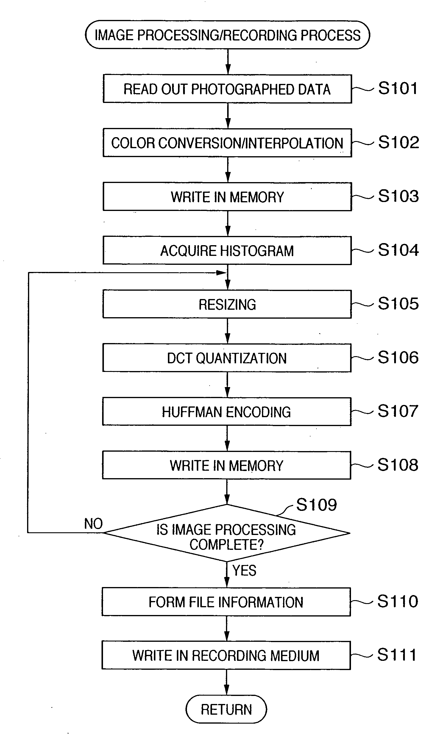
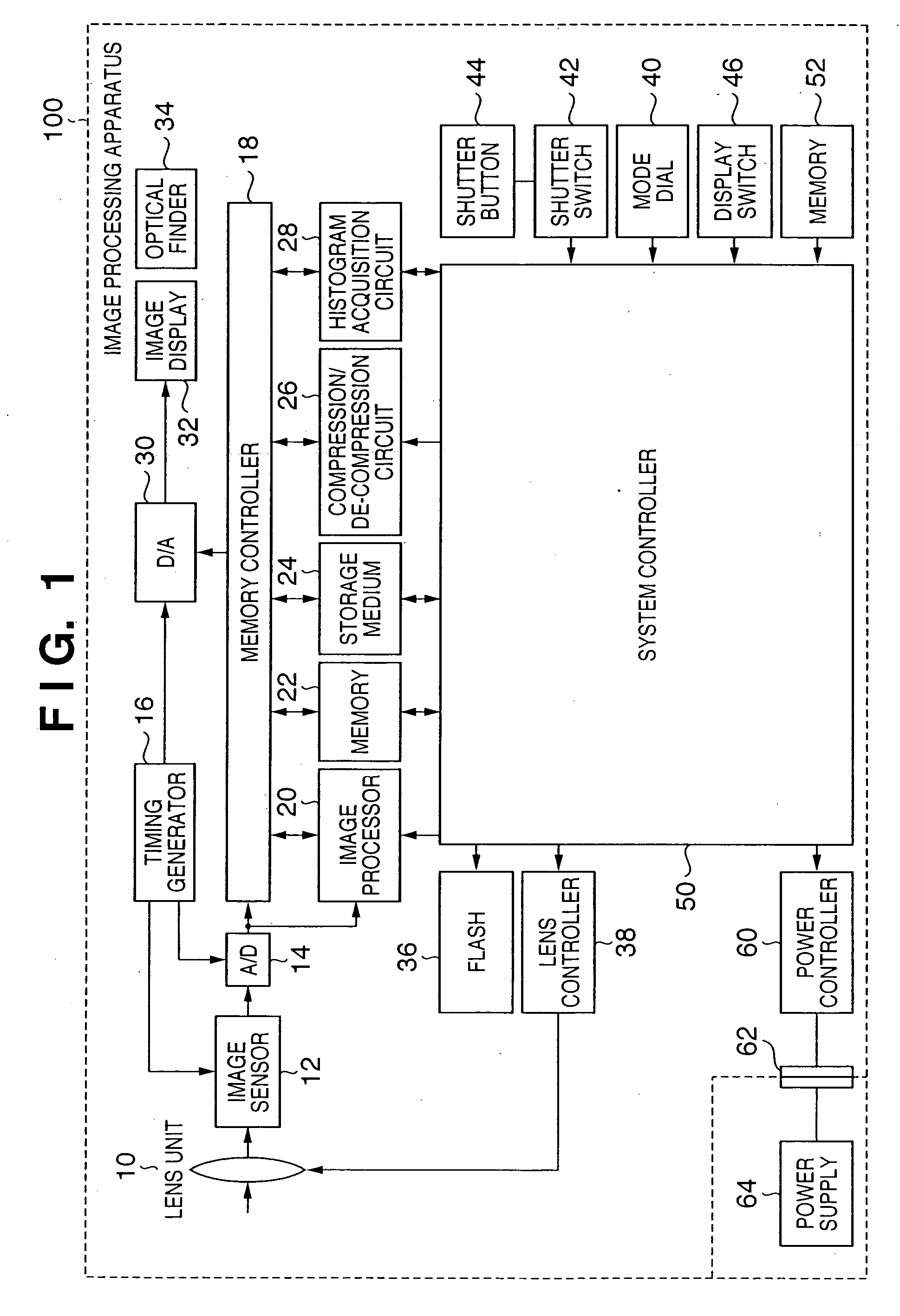
[0046]FIG. 1 is a view showing the arrangement of the first embodiment of an image processing apparatus of the present invention.

[0047] In FIG. 1, reference numeral 10 denotes a lens unit having a zooming mechanism, stop mechanism, and the like; 12, an image sensor (e.g., a CCD) which converts an optical image into an electrical signal; 14, an A / D converter which converts the analog output signal from the image sensor 12 into a digital signal; and 16, a timing generator which supplies clock signals or control signals to the image sensor 12, the A / D converter 14, and a D / A converter 30. The timing generator 16 is controlled by a system controller 50.

[0048] A memory controller 18 controls data transfer between the A / D converter 14, an image processor 20, a memory 22, a recording medium 24, a compression / de-compression circuit 26, the D / A converter 30, and a histogram acquisition circuit 28.

[0049] The output data from the A / D converter 14 is written in the memory 22 or recording med...

second embodiment

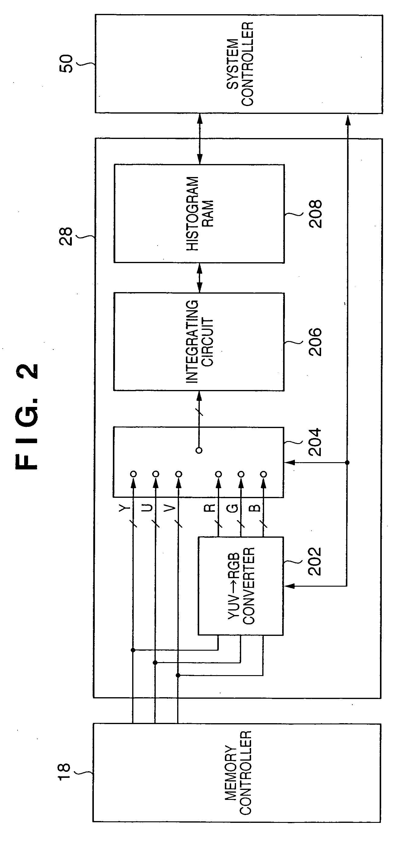
[0118] In the second embodiment, the arrangements of an image processing apparatus and histogram acquisition circuit are apparently the same as the image processing apparatus 100 and histogram acquisition circuit 28 in the first embodiment shown in FIGS. 1 and 2. Therefore, this embodiment will also be described with reference to FIGS. 1 and 2.

[0119] This embodiment differs from the first embodiment in that instead of image data before irreversible compression, YUV data decoded from JPEG data (irreversibly compressed data) by a compression / de-compression circuit 26 is input to a histogram acquisition circuit 28 via a memory controller 18.

[0120] In this embodiment, a histogram is formed from data which is decoded after irreversibly compressed, and this histogram is corrected so as to be close to the histogram of image data before irreversible compression.

[0121] In the second embodiment, in the histogram acquisition circuit 28 shown in FIG. 2, a YUV→RGB converter 202 receives, via ...

third embodiment

[0153] The third embodiment differs from the second embodiment in contents of a histogram correction process. Since the rest of the processing is the same as the second embodiment, an explanation thereof will be omitted.

[0154]FIG. 11 is a flowchart for explaining the histogram correction process in the third embodiment.

[0155] First, a system controller 50 analyzes the dispersion state of histogram information acquired in step S1107 (step S1301).

[0156] This analysis of the dispersion state of the histogram is evaluated by calculating the rate of change in adjacent rate presented below from the acquired histogram.

Adjacent rate change rate [%]=(Hb[i−1] / Hb[i])×100 [0157] Hb[i]: histogram frequency before correction [0158] where i=1 to 255

[0159]FIGS. 13A and 13B each show the rate of change of the adjacent of luminance level. That is, FIG. 13A shows the rate of change of an adjacent of luminance level calculated from the histogram shown in FIG. 12A. FIG. 13B shows the rate of change...


PUM


Abstract

When image data which is decoded after being irreversibly compressed is to be displayed, this invention makes it possible to display a histogram close to the exposure conditions perceived by the human sense during photography. This invention includes a histogram acquisition unit which acquires histogram information from input image data, an encoding unit which generates encoded image data by encoding the input image data or by encoding image data obtained by performing predetermined processing on the input image data, and a recording unit which records the encoded image data and histogram information.

Description

FIELD OF THE INVENTION [0001] The present invention relates to the image processing techniques of still images and moving images. BACKGROUND OF THE INVENTION [0002] In a conventional image processing apparatus such as an electronic still camera, an image signal photographed and output by an image sensor is converted into digital data by an A / D converter, and undergoes necessary image processing in many cases. After that, the image signal undergoes irreversible compression conversion such as JPEG encoding, and is recorded on a recording medium. [0003] The irreversibly compressed image data is read out from the recording medium inside the electronic still camera, decoded (reconstructed), and displayed on a display unit or the like. In this case, it is also possible to obtain histogram information indicating the frequency distribution of the luminance from the decoded playback image data, and display this histogram information together with the decoded image data on the display unit su...

Claims


Application Information

Patent Timeline
IPC IPC(8): G06K9/36
CPCH04N1/32128H04N2101/00H04N2201/3225H04N2201/3277H04N2201/3252H04N2201/3273H04N2201/325
Inventor KOBAYASHI, YOSHIHIRO
Owner CANON KK
Why Eureka
Try Eureka