
Loop ablation apparatus and method

a technology of loop ablation and apparatus, which is applied in the field of electrococcal devices, can solve the problems of cell death, blockage of electrical pathways within the tissue, and leave the structure inta

Inactive Publication Date: 2006-01-12
MEDTRONIC INC
View PDF98 Cites 428 Cited by
  • Summary
  • Abstract
  • Description
  • Claims
  • Application Information

AI Technical Summary

Benefits of technology

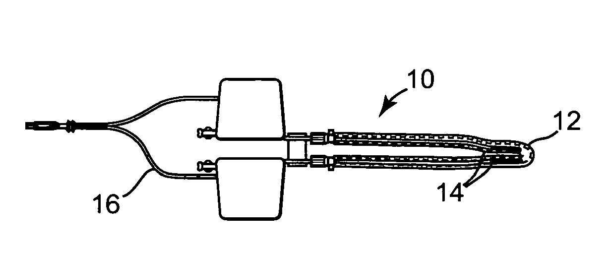
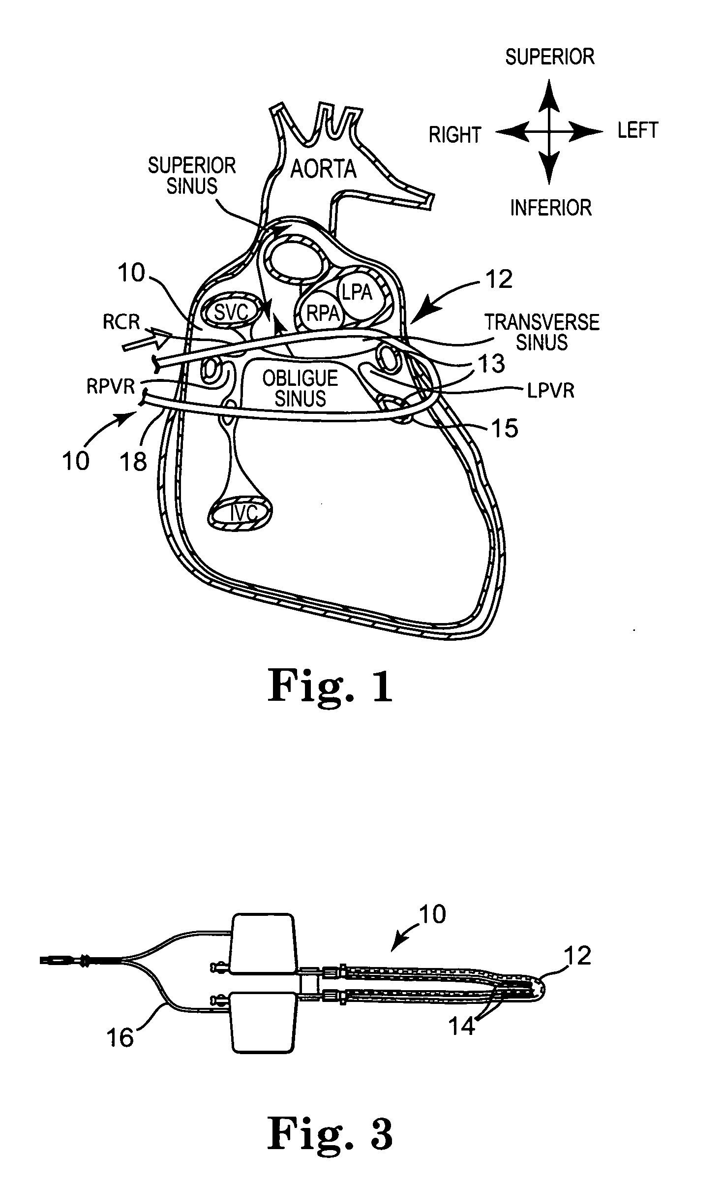
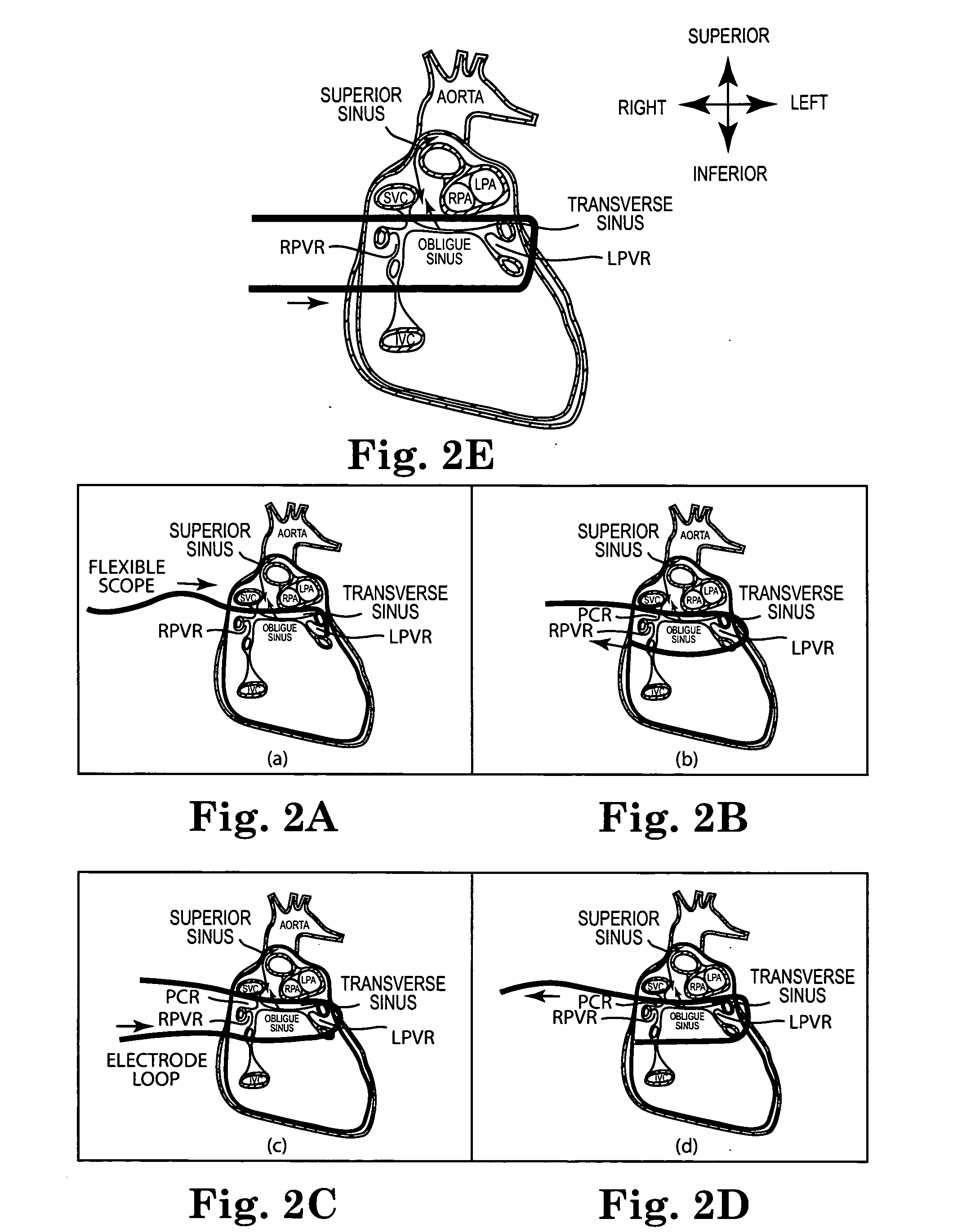
The invention provides an ablation apparatus and method for treating target tissue near pulmonary veins in a patient. The apparatus includes a flexible tube or cannula that can be advanced around the pulmonary veins to form a loop and a roaring mechanism to move the loop over the target tissue. The apparatus also includes carrier elements carrying bipolar electrodes that can be advanced through the loop and rotated to ablate the target tissue. The method involves performing a right thoracotomy and inserting the tube or guide through the superior vena cava into the transverse sinus of the pericardium until it loops around the left pulmonary veins. The guide can then be extended below the inferior vena cava and ablative elements, such as electrodes, can be positioned around the pulmonary veins to ablate the target tissue. The technical effects of the invention include improved ablation of target tissue near pulmonary veins with reduced risk of complications and improved patient outcomes.

Problems solved by technology

With sufficiently high levels of electrical energy between the two electrodes, heat is generated which is sufficient to denature proteins within the tissue and cause cell death.
High levels of voltage can actually cut and remove tissue (i.e., electrosurgery), while lower levels will simply create sufficient heat to cause cell damage, but leave the structure intact (i.e., ablation) and block electrical pathways within the tissue.
Simply placing the jaws onto an endoscopic handle has certain advantages, but there are significant limitations when trying to manipulate both jaws simultaneously through separate tissue spaces.
Loop devices do not all use microwave energy.
Although easy to position within the patient, a significant limitation of these types of loop devices is the ability to reliably create a transmural lesion.
With epicardial systems, it is almost impossible to heat the endocardial layer sufficiently to create a permanent conduction block.
Although this bipolar arrangement is very effective at creating transmural lesions, it tends to be difficult to position within the patient.
Manipulation of the rigid elements is problematic and can lead to tissue trauma.

Method used


Image

  • Loop ablation apparatus and method
  • Loop ablation apparatus and method
  • Loop ablation apparatus and method

Examples


Embodiment Construction

[0114] Before any embodiments of the invention are explained in detail, it is to be understood that the invention is not limited in its application to the details of construction and the arrangement of components set forth in the following description or illustrated in the following drawings. The invention is capable of other embodiments and of being practiced or of being carried out in various ways. Also, it is to be understood that the phraseology and terminology used herein is for the purpose of description and should not be regarded as limited. The use of “including,”“comprising” or “having” and variations thereof herein is meant to encompass the items listed thereafter and equivalents thereof as well as additional items. The terms “mounted,”“connected” and “coupled” are used broadly and encompass both direct and indirect mounting, connecting and coupling. Further, “connected” and “coupled” are not restricted to physical or mechanical connections or couplings, and can include el...


PUM


Abstract

Embodiments of the invention provide an ablation apparatus for ablating target tissue adjacent pulmonary veins of a patient. The ablation apparatus can include a tube capable of being advanced around the pulmonary veins to form a loop. The tube can receive or include electrodes to ablate target tissue. Some embodiments provide a loop ablation device, which may include a cannula and two or more electrode rods carrying two or more bipolar electrodes. The electrode rods can be advanced through the distal ends toward the proximal ends of the loop and toward the target tissue. The bipolar electrodes can receive energy to ablate the target tissue. The bipolar electrodes may be surrounded by the liquid within the cannula while ablating the target tissue. The loop ablation device can further include a rotating grasping mechanism coupled to the electrode rods.

Description

RELATED APPLICATIONS [0001] This application claims the benefit of the filing date of U.S. Provisional Patent Application No. 60 / 576,244 filed on Jun. 2, 2004, which is incorporated herein by reference in its entirety. [0002] This application also claims the benefit of the filing date of U.S. Provisional Patent Application No. 60 / 581,138 filed on Jun. 18, 2004, which is incorporated herein by reference in its entirety.BACKGROUND [0003] Various types of electrocautery devices are used for ablating tissue. Typically, such devices include a conductive tip or blade, which serves as one electrode in an electrical circuit that is completed via a grounding electrode coupled to the patient. With sufficiently high levels of electrical energy between the two electrodes, heat is generated which is sufficient to denature proteins within the tissue and cause cell death. [0004] By controlling the energy level, the amount of heat generated and the degree of tissue damage can also be controlled. Hi...

Claims


Application Information

Patent Timeline
Patent Type & Authority Applications(United States)
IPC IPC(8): A61B18/14
CPCA61B18/1492A61B2018/00291A61B2018/00363A61B2018/1472A61B2018/00577A61B2018/1407A61B2018/00375
Inventor CHRISITIAN, STEVEN C.FRANCISCHELLI, DAVID E.PODBELISKI, ADAM A.HAEG, DANIEL CHARLESSTEINBRINK, MARIE T.BRISCOE, RODERICK E.DAIGLE, TOM P.
Owner MEDTRONIC INC
Learn More