Wick to reduce liquid flooding and control release rate

a technology of liquid flooding and wicks, applied in the field of wicks, can solve the problems of difficult to achieve the proportion of wicks without porosity, and achieve the effects of reducing flooding, improving liquid delivery, and reducing flow rate through wicks

Inactive Publication Date: 2006-01-19
VARANASI PADMA PRABODH +1
View PDF10 Cites 25 Cited by
  • Summary
  • Abstract
  • Description
  • Claims
  • Application Information

AI Technical Summary

Benefits of technology

[0009] Our invention addresses the problems mentioned above by improving the delivery of liquid through a wick. More preferably, our invention is an improved wick for delivery of liquids from a reservoir (preferably, to an orifice plate in an atomizer device). More specifically, our invention reduces the flow rate through the wick to reduce flooding, while maintaining a flow rate suitable for atomization, as well as the preferred size and rigidity of the wick.

Problems solved by technology

Most preferably, the non-porous portion is completely non-porous; however, as a practical matter, a portion of wick with no porosity may be difficult to achieve, given manufacturing limitations.

Method used


Image

  • Wick to reduce liquid flooding and control release rate
  • Wick to reduce liquid flooding and control release rate
  • Wick to reduce liquid flooding and control release rate

Examples


Embodiment Construction

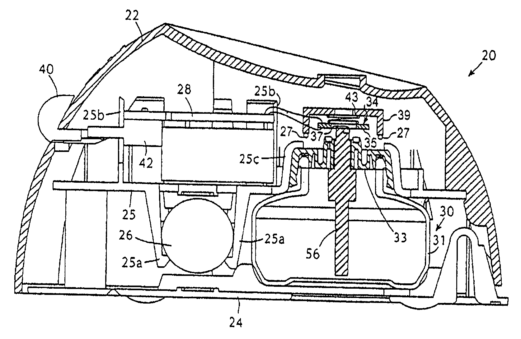
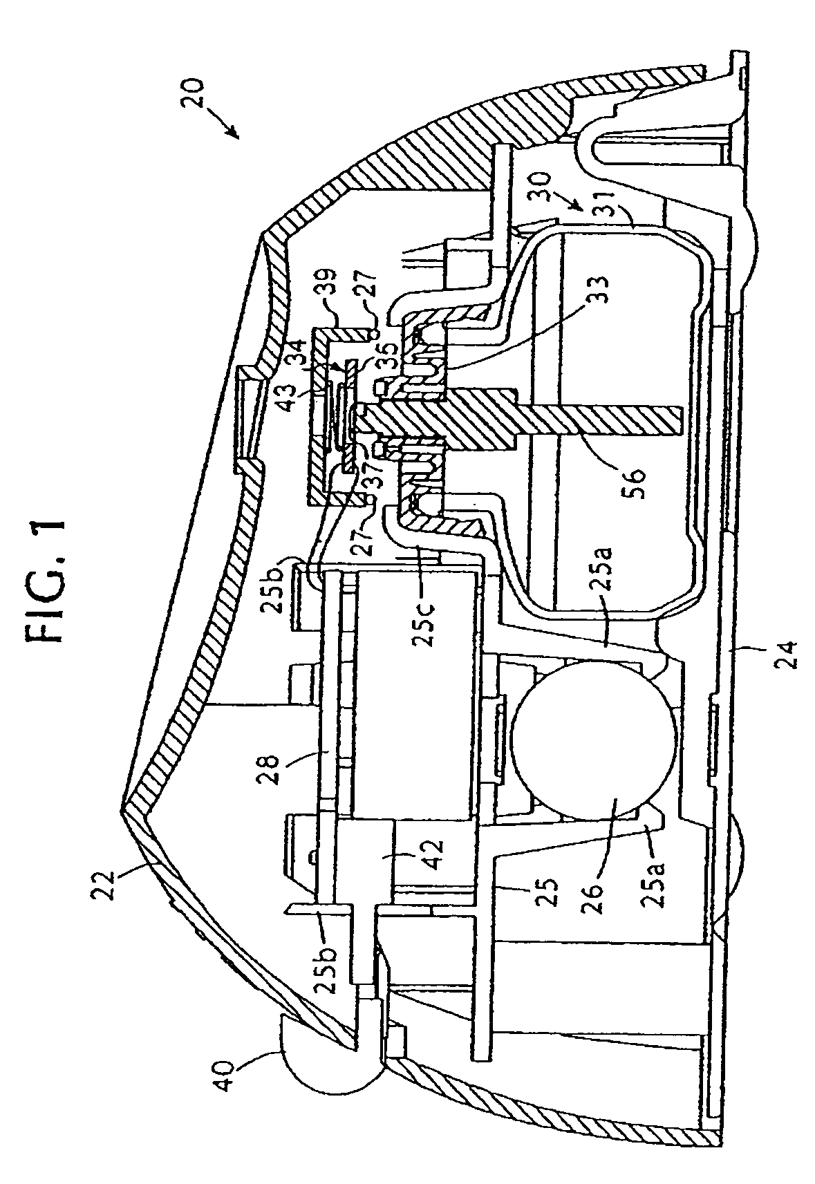
[0019] The preferred use of the wick described in this invention is for transporting liquid from a reservoir to an orifice plate in an atomization device. As shown in FIG. 1, an atomization device 20 according to our invention typically comprises an atomizer assembly 34, which includes an orifice plate 37, and a replaceble reservoir assembly 30. The reservoir assembly 30 includes a reservoir 31 containing fluid and a wick 56.

[0020] The piezoelectrically actuated atomization device 20 according to a preferred embodiment of our invention comprises a housing 22 formed as a hollow plastic shell and closed by a flat bottom wall 24. A horizontal platform 25 extends across the interior of the housing 22. A battery 26 is supported by means of support prongs 25a which extend down from the underside of the platform 25 inside the housing 22. In addition, a printed circuit board 28 is supported on support elements 25b which extend upwardly from the platform 25. A liquid reservoir assembly 30 i...


PUM

PropertyMeasurementUnit
diameteraaaaaaaaaa
lengthaaaaaaaaaa
diameteraaaaaaaaaa

Abstract

A solid, dimensionally stable wick including a porous portion having capillary passages for drawing a liquid from a lower end to an upper end, and a substantially non-porous portion that has not more than about five percent by volume porosity. The wick is particularly useful in supplying fluid to an atomization device from a reservoir.

Description

CROSS-REFERENCE TO RELATED APPLICATION [0001] This application claims the benefit of, and incorporates by reference, U.S. Provisional Patent Application No. 60 / 583,787, filed Jun. 30, 2004.BACKGROUND OF THE INVENTION [0002] 1. Field of the Invention [0003] This invention relates to wicks used for transporting liquids. Specifically, this invention relates to a wick-based delivery system for transporting liquids, such as fragrances or insecticides, from a reservoir to the ambient environment. Preferably, the liquids are transported to the surface of an orifice plate which atomizes the liquid and ejects the atomized droplets into the ambient air. [0004] 2. Description of the Related Art [0005] Devices that dispense vapors into the ambient air are well-known in the art and useful in many applications. Generally, the purpose of these devices is to deodorize or disinfect the ambient air, or to distribute toxins into the air to kill or repel unwanted pests. [0006] A common method of disper...

Claims


Application Information

Patent Timeline
Patent Type & Authority Applications(United States)
IPC IPC(8): B05B17/04A61L9/03A61L9/12
CPCA01M1/205A61L9/127B05B17/0684A61L2209/132B05B17/0638A61L9/14A61L9/12
Inventor VARANASI, PADMA PRABODHADAIR, JOEL E.
Owner VARANASI PADMA PRABODH
Why Eureka
Try Eureka