Actuator integrally provided with fail-safe function

a technology of fail-safe function and actuator, applied in the direction of mechanical energy handling, mechanical apparatus, operating means/releasing devices of valves, etc., can solve the problems of complex system and deterioration of maintenance workability, and achieve the effect of safe condition

Active Publication Date: 2006-01-19
MINEBEAMITSUMI INC
View PDF8 Cites 4 Cited by
  • Summary
  • Abstract
  • Description
  • Claims
  • Application Information

AI Technical Summary

Benefits of technology

[0022] In the aspect of the present invention, the actuator may further comprise a sealing member disposed around the housing. This structure seals up a gap between the housing and the equipment applied, thus a safe condition is ensured.

Problems solved by technology

In the gas shutoff valve system shown in FIG. 7 as disclosed in the aforementioned Japanese Patent Application Laid-Open No. 2003-042324, the spring 105 to press the valve plug 102 against the valve seat 101 is provided in a gas channel 114, which makes the system complicated, and the spring 105 is difficult to replace, which results in deteriorated workability in maintenance.

Method used


Image

  • Actuator integrally provided with fail-safe function
  • Actuator integrally provided with fail-safe function
  • Actuator integrally provided with fail-safe function

Examples


first embodiment

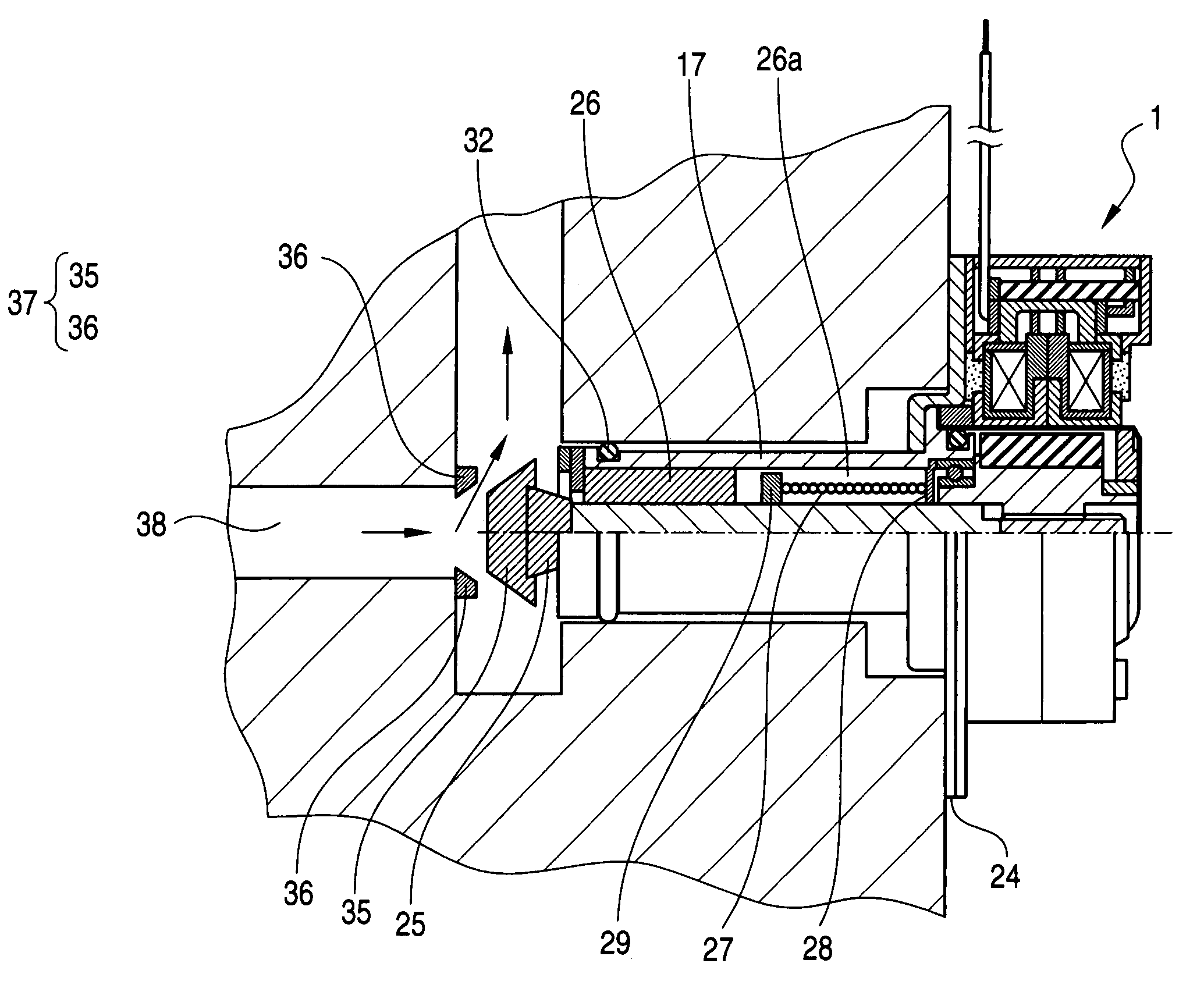
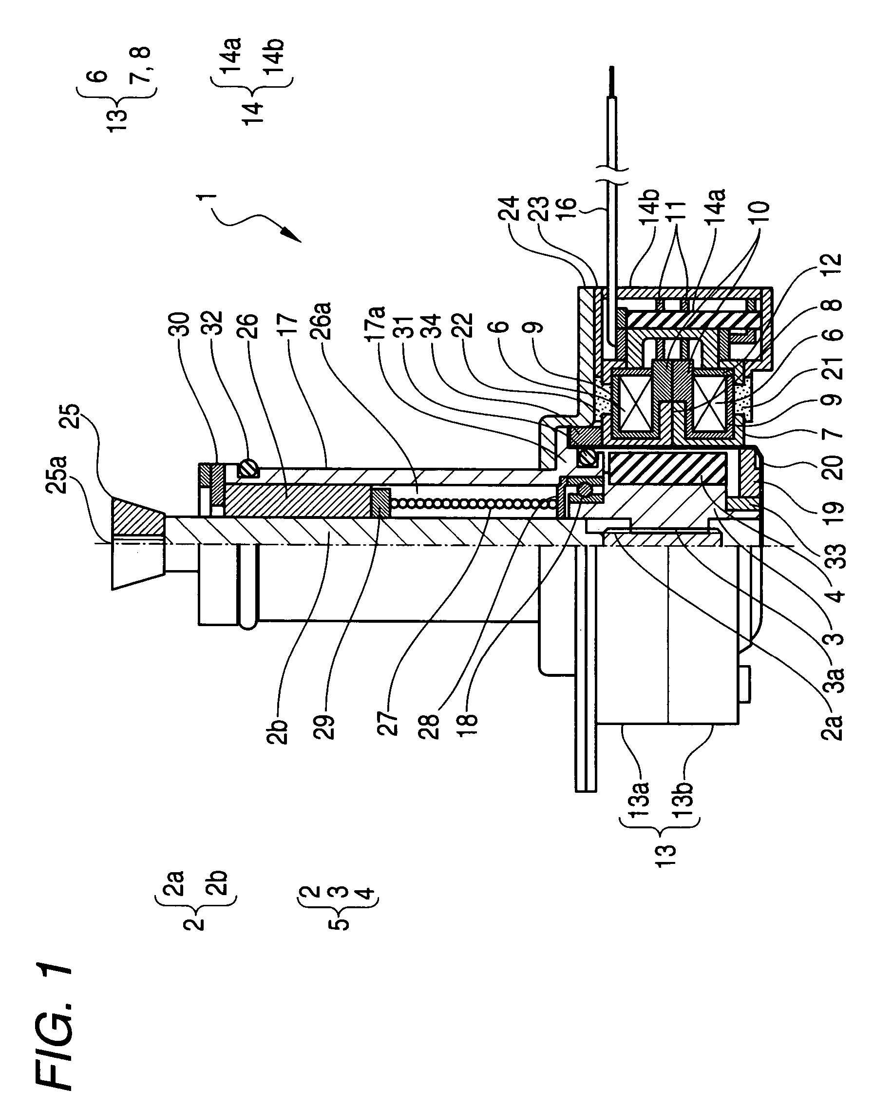
[0032] Referring to FIG. 1, an actuator 1 according to the present invention generally comprises a rotor assembly 5, a stator assembly 13, and a housing 17.

[0033] The rotor assembly 5 includes an output shaft 2, a sleeve 3, and a magnet 4 with multi-polar magnetization. The output shaft 2 has a screw portion 2a and a plain rod portion 2b, the sleeve 3 is formed of synthetic resin and has a screw portion 3a located at an elevated portion on its inner circumferential surface, and the magnet 4 is shaped hollow-cylindrical and fixedly disposed at the outer circumference of the sleeve 3. The screw portion 2a is located at a portion of the outer circumferential surface of the output shaft 2 and engages threadedly with the screw portion 3a of the sleeve 3. A head piece 25 is attached to an open end of the plain rod portion 2b of the output shaft 2, and a valve plug (not shown in FIG. 1) is attached to the head piece 25 so as to oppose a valve seat (not shown in FIG. 1) disposed in a fluid ...

second embodiment

[0078] In the second embodiment described above, the stopper plate 28 is not absolutely required if the pin 29 is otherwise stopped so as to be prohibited from coming into contact with the end of the sleeve 3 including the bearing 18.

[0079] In the embodiments described above, an extension coil spring is used for a fail-safe operation in case of emergency, but the present invention is not limited to use of an extension coil spring but may alternatively use a compression coil spring which is extended by application of an external force and is restored for contraction by release of the external force.

[0080] When a compression coil spring is used, components must be attached to the compression coil spring in such a manner as to allow its spring force to duly act on the components. Specifically, for example in case of the first embodiment shown in FIG. 1, both ends of the compression coil spring are engagingly attached to the stopper plate 28 and the pin 29, respectively, and in case of...


PUM


Abstract

An actuator includes: a rotor assembly including an output shaft having a male screw portion and having a pin attached thereto, and a sleeve having a female screw portion and threadedly engaged with the male screw portion of the output shaft so as to convert a rotary motion of the sleeve into a linear motion of the output shaft; a stator assembly disposed around the rotor assembly; a housing attached to the stator assembly; a coil spring; and a spring holder having slits to guide the pin into an axial direction. In the actuator, the coil spring and the spring holder constitute a fail-safe mechanism and are contained inside the housing, and the coil spring is arranged at such a location that the output shaft is caused to move in a direction to achieve a fail-safe operation. Thus, the actuator incorporates a fail-safe mechanism as an integral unit.

Description

BACKGROUND OF THE INVENTION [0001] 1. Field of the Invention [0002] The present invention relates to an actuator for a flow control valve to control flow in a fluid channel, and more particularly to an actuator integrally provided with a fail-safe function to mandatorily actuate a valve so as to provide a safe condition for a fluid channel when electric power supply is accidentally cut off for some reason. [0003] 2. Description of the Related Art [0004] A flow control valve is conventionally used for gas flow control performed with a shutoff valve provided in a fluid channel of a gas supply equipment, and also for switching control of a refrigerant channel for air-conditioning. Such a flow control valve is driven by an actuator in which that the rotary motion of a motor shaft is converted into the linear motion of a valve by means of a pinion gear or a screw structure. [0005] Recently, a permanent magnet (PM) type stepping motor, which achieves a high positioning accuracy by means o...

Claims


Application Information

Patent Timeline
Patent Type & Authority Applications(United States)
IPC IPC(8): F16K31/02
CPCF16K31/047H02K7/06F16K31/508
Inventor SUZUKI, YUZURU
Owner MINEBEAMITSUMI INC
Why Eureka
Try Eureka