Power take off

a power take off and assembly technology, applied in the field of power take off assemblies and saws, can solve the problems of large engine and often larger sawing dimensions, less maneuverability, and large sawing, and achieve the effect of small profile, same overall sawing dimension, and higher horsepower

Inactive Publication Date: 2006-01-19
HUSQVARNA OUTDOOR PROD INC
View PDF17 Cites 1 Cited by
  • Summary
  • Abstract
  • Description
  • Claims
  • Application Information

AI Technical Summary

Benefits of technology

[0010] Apparatus and methods are described for providing a saw with a smaller profile. A saw and method of operation are also provided that would allow a higher horsepower engine with the same overall saw dimension as conventional saws, or even smaller. A saw and saw operating method are shown that separate the drive function for the saw output and the support function for the saw output, or reducing the load function of the stub shaft so the primary function of the stub shaft is to turn the output sheave. Additionally, a saw and operating method are further described that reduces cyclical fatigue on the rotating shaft, and that may also reduce load placed on the engine crank shaft. Engine operation and performance can be improved and made more reliable, engine horsepower can be increased without adversely affecting the overall size of the saw, and in some cases, the saw size can be reduced.

Problems solved by technology

However, higher horsepower levels usually mean larger engines and often larger saw dimensions.
Larger saws may also mean less maneuver ability.
In some applications, structures may be such that access to an area for cutting may be limited.
However, the equipment to be used for cutting in those areas may be limited by such restrictions as access opening size, elevator size and the like.
Therefore, the amount of horsepower for a saw and other operating characteristics such as blade size and the like may be limited for a given application by such factors as access opening size and the like.
Increasing the horsepower for a saw often results in a larger saw.
If the engine is made larger, the width of the engine with the stub shaft typically increases, which may make the saw less maneuverable.
Therefore, saw improvements may have undesirable consequences for some users.
Such loads sometimes produce fatigue and sometimes fractures in the shaft, leading to drive failure.
Increasing the saw horsepower produces more cyclical fatigue loads on the shaft and may increase the likelihood of shaft failure.

Method used


Image

  • Power take off
  • Power take off
  • Power take off

Examples


Embodiment Construction

[0032] The following specification taken in conjunction with the drawings sets forth the preferred embodiments of the present inventions in such a manner that any person skilled in the art can make and use the inventions. The embodiments of the inventions disclosed herein are the best modes contemplated by the inventor for carrying out the inventions in a commercial environment, although it should be understood that various modifications can be accomplished within the parameters of the present inventions.

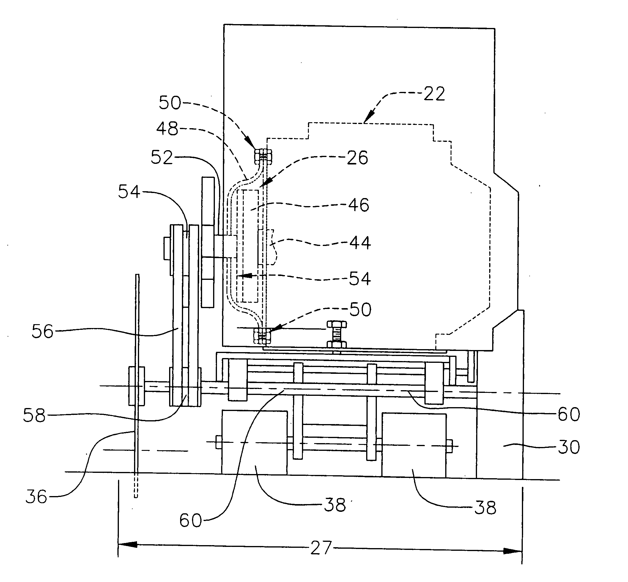
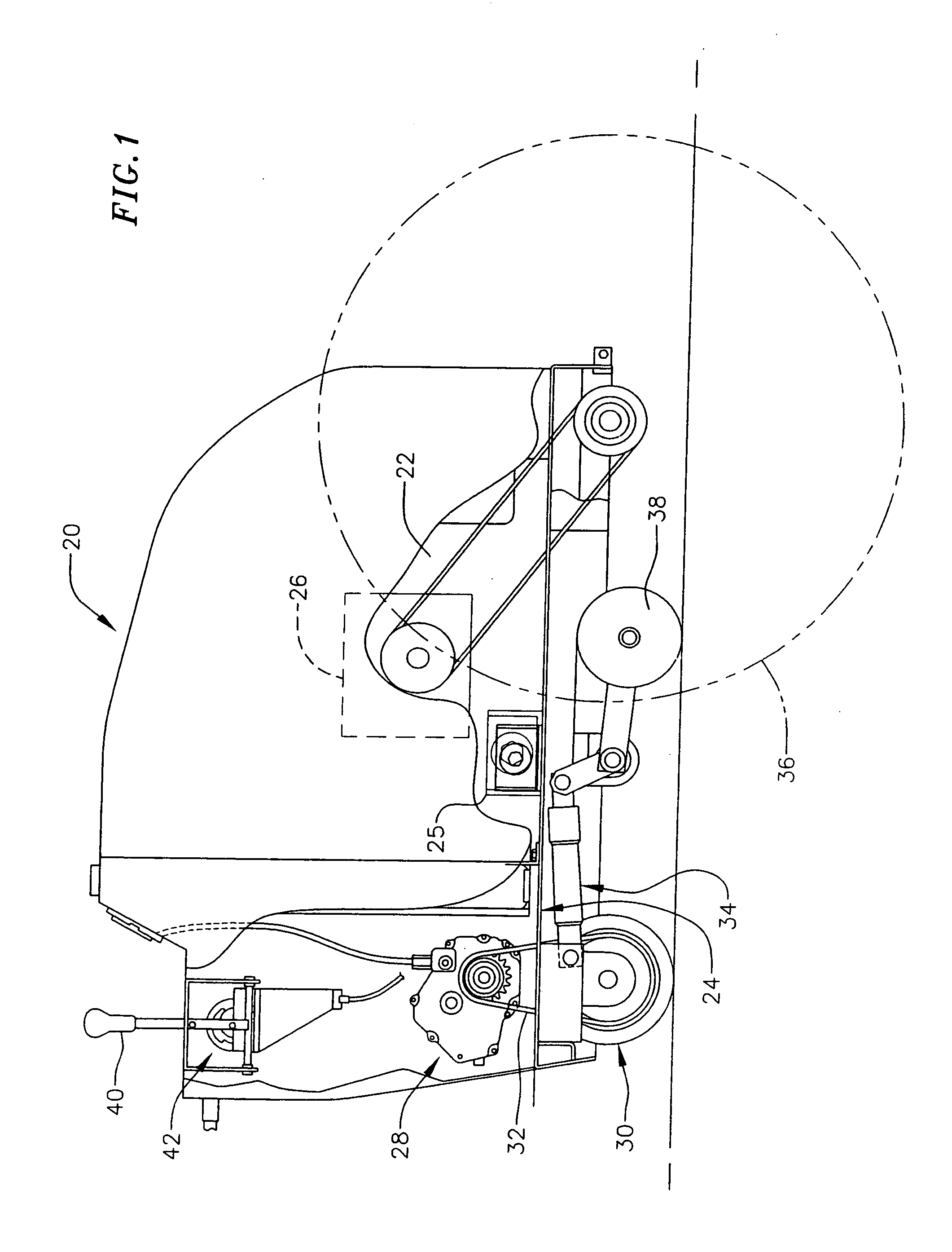
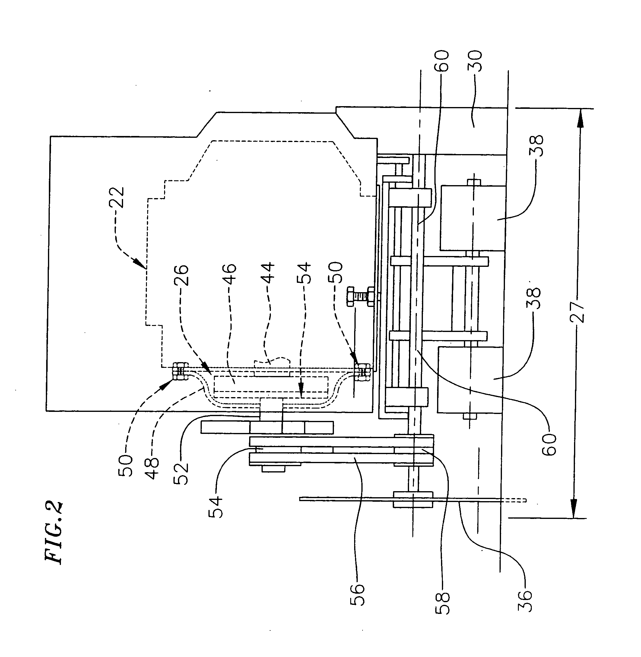
[0033] Mechanical drives and power takeoff assemblies find applications in a number of areas. For the present descriptions, examples of power takeoff assemblies will be given in the context of flat saws or concrete slab saws such as those used to cut pavement, concrete in buildings and other structures, and the like. However, it should be understood that the inventions are not limited to the examples, and can be extended and are applicable to other methods and apparatus as well.

[0...


PUM

PropertyMeasurementUnit
widthaaaaaaaaaa
flexibleaaaaaaaaaa
lengthaaaaaaaaaa

Abstract

A power takeoff assembly, a drive assembly, a saw and a kit for a saw include a drive plate and drive shaft, for example for mounting to a fly wheel, and a bell housing for mounting to an engine block and for supporting a sheave. The sheave rotates on bearings supported by a housing tube on the bell housing, and a coupler couples the drive shaft, which extends into the tube, to the sheave. Side loading and cyclical loading on the drive shaft are reduced, dimensions of the saw can be reduced and operation of the saw can be more reliable.

Description

CROSS-REFERENCE TO RELATED APPLICATION [0001] This is a continuation of Ser. No. 10 / 100,502, filed Mar. 18, 2002, now U.S. Pat. No. 6,945,608, incorporated herein by reference.BACKGROUND OF THE INVENTIONS [0002] 1. Field of the Invention [0003] This relates to power take off assemblies, and saws using power take off assemblies, for example concrete and slab saws and self propelled saws. [0004] 2. Related Art [0005] Power saws typically include a motor, engine or other system for producing drive power, a saw blade or other cutting device and a support frame structure for supporting the engine and cutting blade. The power system may be an internal combustion engine, a hydraulic motor, an electric motor or the like. The power system can drive the cutting blade through a mechanical or hydraulic drive system, but a belt drive system is common. The size and dimensions of the saw will vary according to usage and application. [0006] For large projects, higher horsepower levels are desired f...

Claims


Application Information

Patent Timeline
Patent Type & Authority Applications(United States)
IPC IPC(8): E21C25/00B23D47/12B28D1/04
CPCB23D47/12Y10T403/19B28D1/045
Inventor BARATTA, ANTHONYPETERSON, STANCUEVAS, LUCIANOFARRIS, MATT
Owner HUSQVARNA OUTDOOR PROD INC
Why Eureka
Try Eureka