
Discharge lamp lighting apparatus for lighting multiple discharge lamps

a technology of lighting apparatus and discharge lamp, which is applied in the direction of electric variable regulation, process and machine control, instruments, etc., can solve the problems of increasing the cost of the apparatus, affecting the operation of the apparatus, and affecting the operation of the lighting apparatus, etc., and achieves the effect of high efficiency, simplified circuitry and low cos

Inactive Publication Date: 2006-01-19
MINEBEA CO LTD
View PDF12 Cites 2 Cited by
  • Summary
  • Abstract
  • Description
  • Claims
  • Application Information

AI Technical Summary

Benefits of technology

[0010] The present invention has been in light of the problems described above, and it is an object of the present invention to provide a discharge lamp lighting apparatus which realizes a blinking lighting inexpensively and efficiently.
[0016] According to the discharge lamp lighting apparatus of the present invention, since only one control circuit can controllably light on and off a plurality of discharge lamps, a blinking lighting operation is realized inexpensively by a highly efficient separate oscillating inverter, and the circuitry is simplified thus allowing the discharge lamp lighting apparatus to be readily downsized.

Problems solved by technology

Such an LCD apparatus advantageously has a thinner profile and lower power consumption than a CRT conventionally used, but incurs a deteriorated image quality due to a blurred outline in a movie display.
The discharge lamp lighting apparatus 100 shown in FIG. 3 requires a plurality of control IC's in order to light on and off the plurality of discharge lamps, thus increasing the cost of the apparatus.
The discharge lamp lighting apparatus 200 shown in FIG. 4, which does not requires a control IC and therefore is advantageous in cost compared to the apparatus 100, incurs a large loss due to heat generated, and the like, thus raising a problem in efficiency.

Method used


Image

  • Discharge lamp lighting apparatus for lighting multiple discharge lamps
  • Discharge lamp lighting apparatus for lighting multiple discharge lamps
  • Discharge lamp lighting apparatus for lighting multiple discharge lamps

Examples


Embodiment Construction

[0022] A preferred embodiment of the present invention will hereinafter be described with reference to the accompanying drawings.

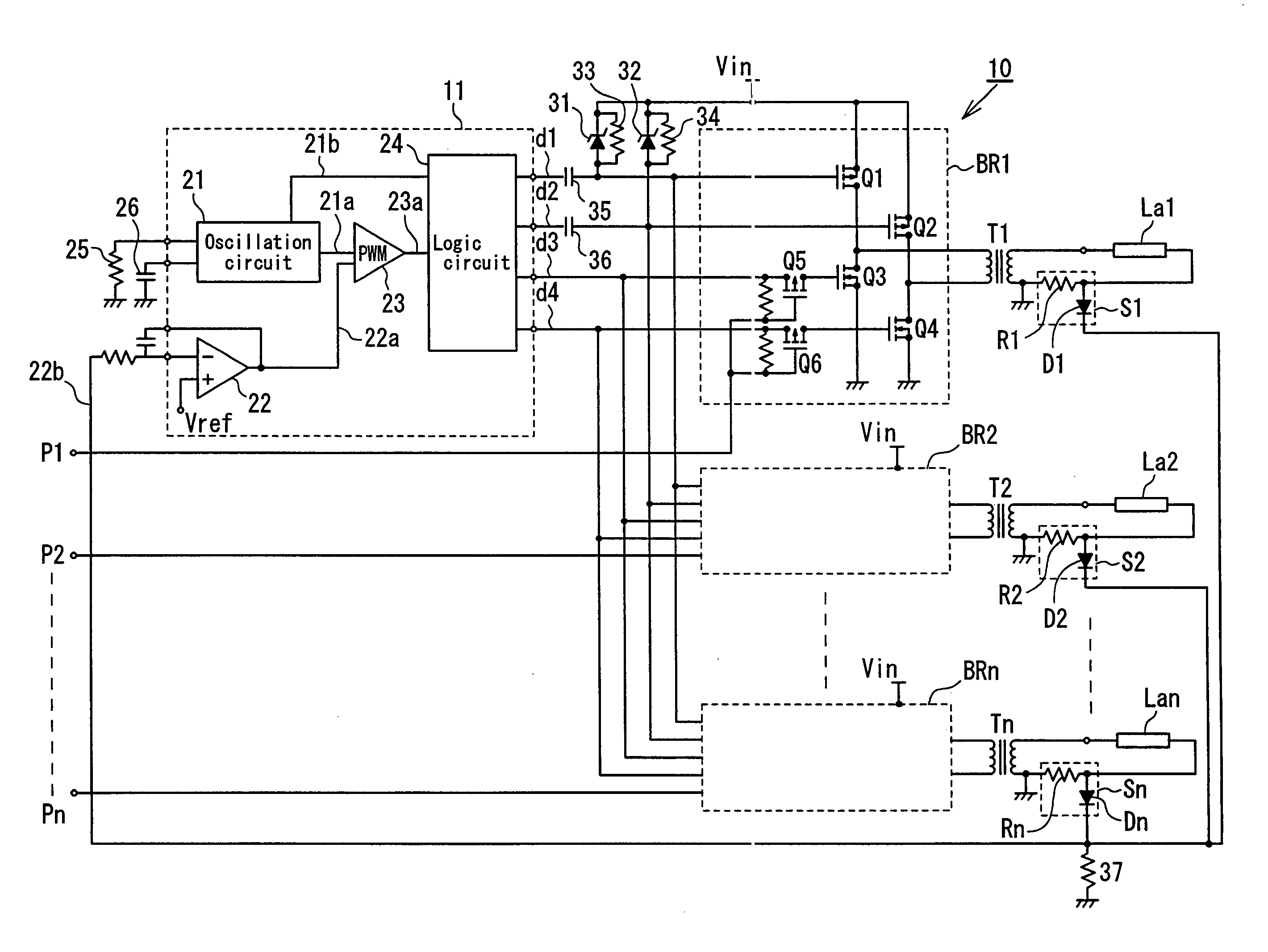
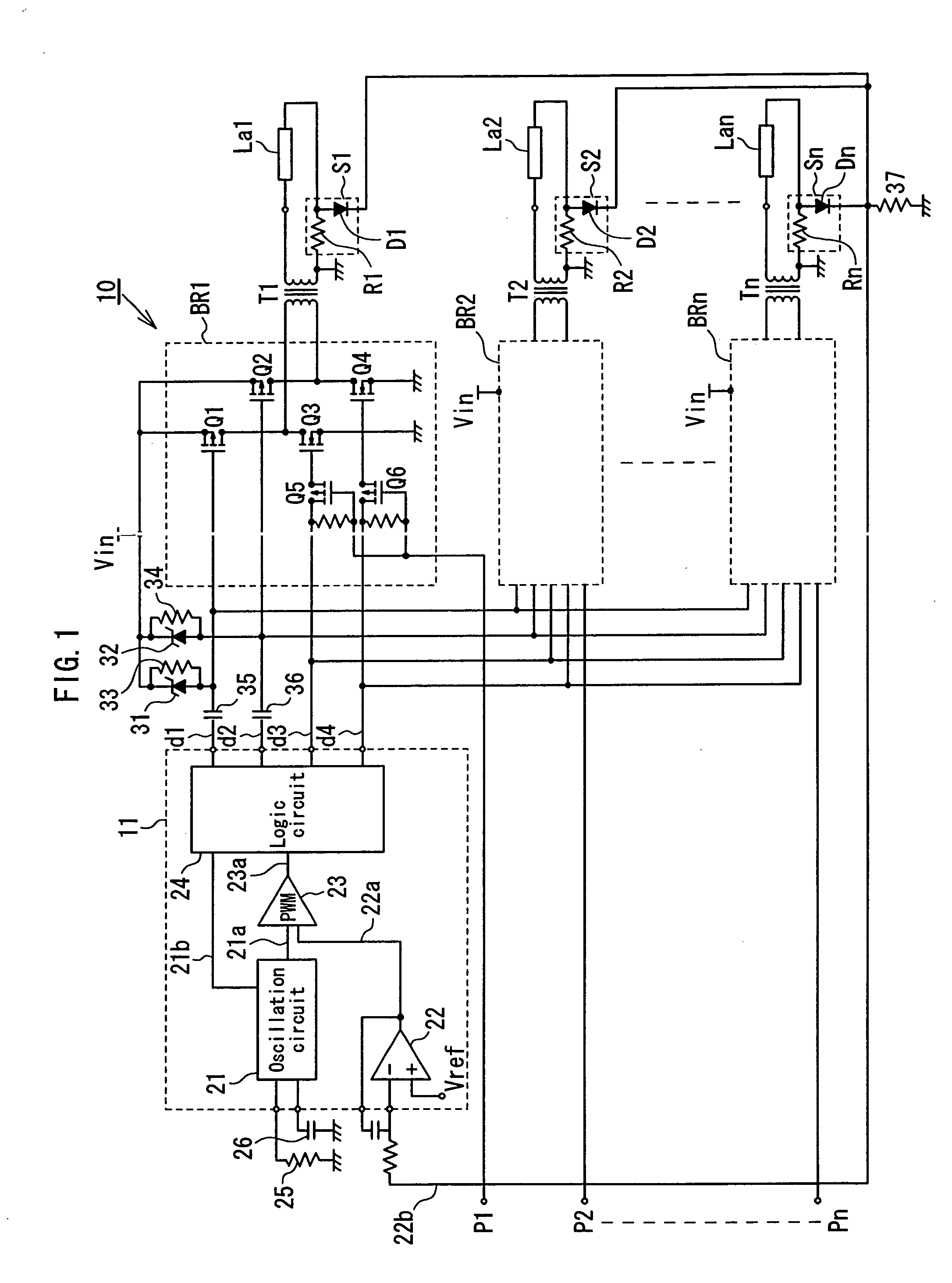
[0023] Referring to FIG. 1, a discharge lamp lighting apparatus 10 according to an embodiment of the present invention is for controllably lighting a plurality of discharge lamps (for example, cold-cathode tubes) La1 to Lan, and includes a control circuit 11, a plurality of bridge circuits BR1 to BRn, and a plurality of step-up transformers T1 to Tn.

[0024] Each of the bridge circuits BR1 to BRn includes a series circuit consisting of switching elements Q1 and Q3, and a series circuit consisting of switching elements Q2 and Q4, wherein the series circuits are connected in parallel to each other and have their one terminals connected to a DC power supply Vin and have the other terminals grounded, and the connection portion of the switching elements Q1 and Q3 and the connection portion of the switching elements Q2 and Q4 are connected respectively to both t...


PUM


Abstract

A discharge lamp lighting apparatus for lighting a plurality of discharge lamps comprises: a control circuit adapted to output driving signals; a plurality of step-up transformers; and a plurality of bridge circuits, each of which is connected to a DC power supply, and drives the primary side of each of the step-up transformers according to the driving signals from the control circuit so as to light each of the discharge lamps connected respectively to the secondary sides of the step-up transformers. In the discharge lamp lighting apparatus, each of the bridge circuits is connected to the control circuit via synchronous switching elements, and the synchronous switching elements, according to each of synchronizing signals applied thereto, switch on and off the driving signals from the control circuit so as to controllably cause each of the bridge circuits to start and stop its operation.

Description

BACKGROUND OF THE INVENTION [0001] 1. Field of the Invention [0002] The present invention relates to a discharge lamp lighting apparatus, and more particularly to a discharge lamp lighting apparatus adapted to light multiple discharge lamps for use as a backlight in a liquid crystal display apparatus. [0003] 2. Description of the Related Art [0004] A liquid crystal display (LCD) apparatus is extensively used in electronics devices, and is increasingly superseding a cathode ray tube (CRT) in a relatively large-screen display apparatus such as a personal computer, and a TV set. In such a large-screen LCD apparatus, a backlight system provided with a plurality of discharge lamps is generally used in order to ensure a sufficient display brightness and also uniformity in the brightness, and the discharge lamps are usually driven by a discharge lamp lighting apparatus having an inverter circuit. [0005] Such an LCD apparatus advantageously has a thinner profile and lower power consumption ...

Claims


Application Information

Patent Timeline
IPC IPC(8): H05B37/02
CPCH05B41/282Y02B20/183H05B41/3927H05B41/2828Y02B20/00
Inventor SUZUKI, SHINICHI
Owner MINEBEA CO LTD
Learn More