
PxM antenna for high-power, broadband applications

Inactive Publication Date: 2006-01-19
TDK CORPARATION
View PDF8 Cites 16 Cited by
  • Summary
  • Abstract
  • Description
  • Claims
  • Application Information

AI Technical Summary

Benefits of technology

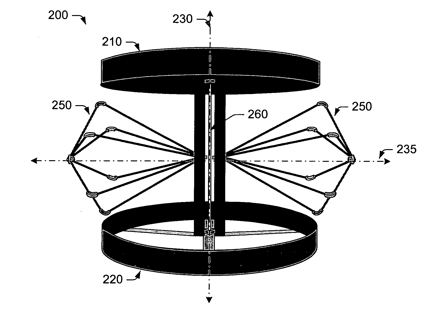
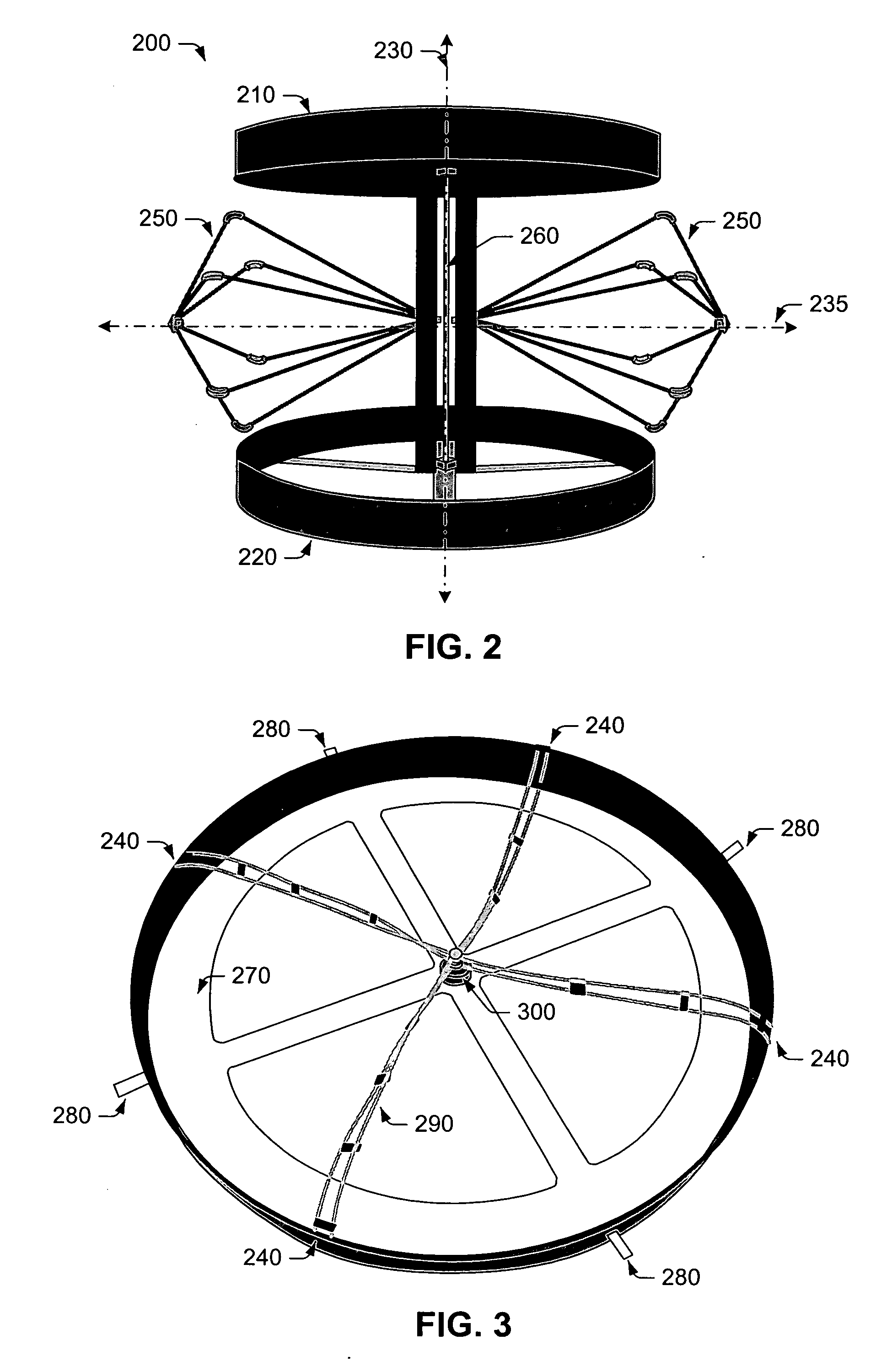
[0020] The problems outlined above may be in large part addressed by an antenna that includes a pair of magnetic loops arranged within two spaced-apart, parallel planes. The magnetic loops may be aligned along an axis extending through center points of each of the magnetic loops and may include multiple feed points, which are symmetrically spaced about the axis. For this reason, the magnetic loops may be alternatively referred to as “multiply-fed” loops. Substantially any number of feed points may be included on each multiply-fed loop, depending on the desired operating frequency range. In some embodiments, the number of feed points may range between about 2 to 16 feed points. In one embodiment, four feed points may be symmetrically arranged around each loop. However, a greater / lesser number of feed points may be used to increase / decrease the usable bandwidth of the antenna. Regardless of the number of feed points used, stacking of the magnetic loops advantageously functions to reduce the radiation Q and extend the bandwidth of the antenna.

Problems solved by technology

However, a greater / lesser number of feed points may be used to increase / decrease the usable bandwidth of the antenna.

Method used


Image

  • PxM antenna for high-power, broadband applications
  • PxM antenna for high-power, broadband applications
  • PxM antenna for high-power, broadband applications

Examples


Embodiment Construction

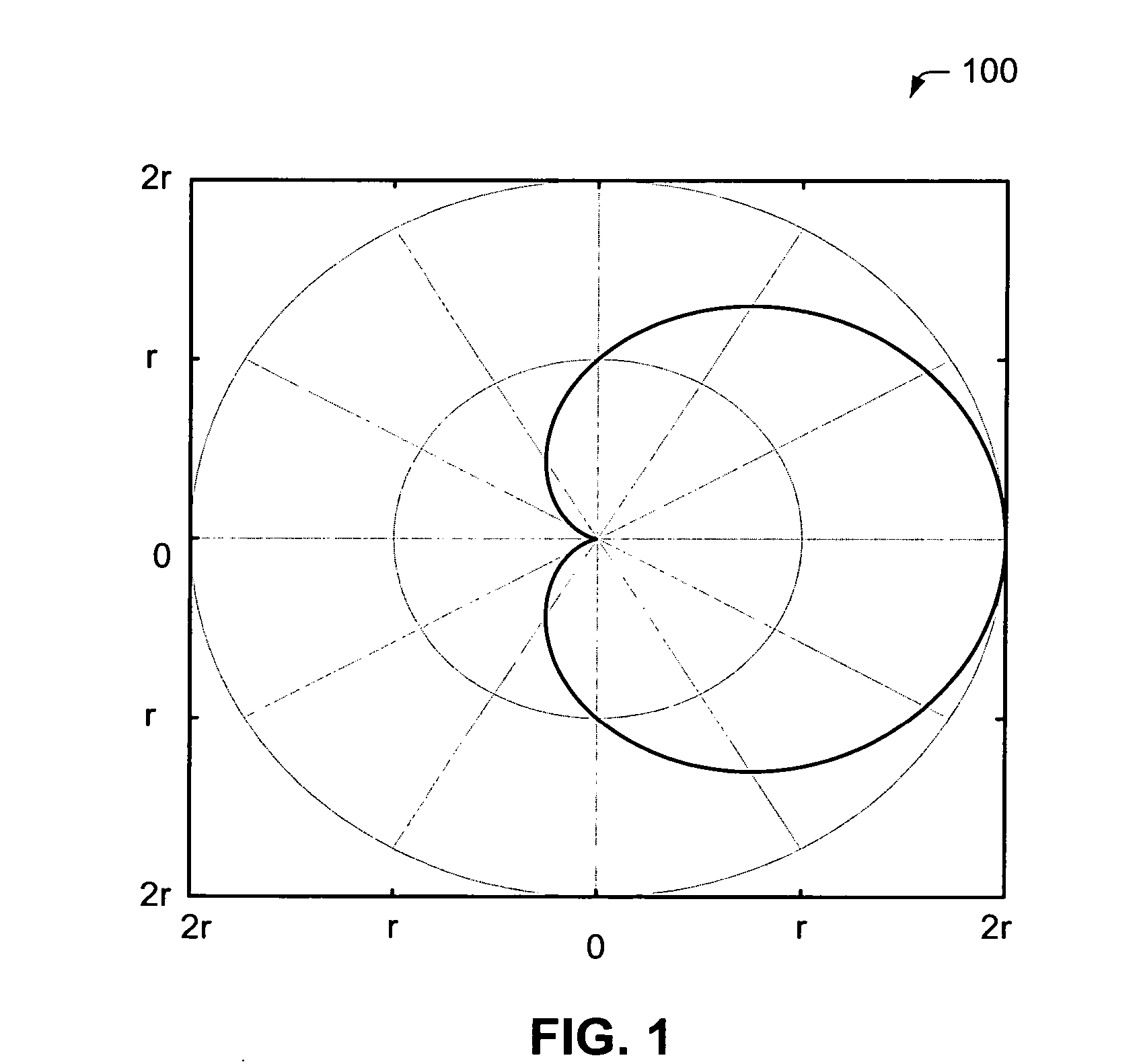
[0033] P×M antennas, so called because they are derived from an orthogonal combination of electric and magnetic radiators, possess several desirable characteristics including, but not limited to, a useful radiation pattern and relatively broad impedance bandwidth for a given electrical size. One form of the P×M antenna exhibits the radiation pattern of a hypothetical Huygens source. The radiation pattern, also referred to as the Ludwig-3 pattern, is a linearly-polarized unidirectional pattern comprised of a cardioid of revolution about the axis of maximum radiation intensity, and falls into the class of so-called maximum directivity patterns. As used herein, a “cardioid” is described as a heart-shaped curve traced by a point on the circumference of a circle rolling completely around another circle of fixed radius (r), and has the general equation of:

ρ=r*(1+cos θ)  (EQ. 3)

in polar coordinates. A polar plot of a cardioid-shaped radiation pattern 100 is shown in FIG. 1. In the foreg...


PUM


Abstract

A broadband antenna including both electric and magnetic dipole radiators is provided herein. The broadband antenna may be referred to as a “P×M antenna” and may include a pair of magnetic loop elements, each having multiple feed points symmetrically spaced around the loop element. The broadband antenna may also include an electric dipole element arranged between the pair of magnetic loop elements. In general, the electric dipole element and the magnetic loop elements may be coupled together through a network of transmission lines, as opposed to being incorporated into a single radiative element.

Description

PRIORITY APPLICATION [0001] This application claims priority to Provisional Application No. 60 / 587,318 entitled “P×M Antenna for High-Power, Broadband Applications,” filed Jul. 13, 2004.BACKGROUND OF THE INVENTION [0002] 1. Field of the Invention [0003] This invention relates to antennas and, more particularly, to a practical implementation of a low-loss, broadband antenna incorporating electric and magnetic radiative components. [0004] 2. Description of the Related Art [0005] The following descriptions and examples are not admitted to be prior art by virtue of their inclusion within this section. [0006] Electrically-small antenna elements are utilized in many low frequency (e.g., mobile communications) and high frequency (e.g., EMC testing) applications. For example, an electrically-small antenna may be used in low frequency applications to accommodate space, durability or other concerns, or in high frequency applications to achieve a particular frequency level, which may be desire...

Claims


Application Information

Patent Timeline
IPC IPC(8): H01Q11/12H01Q7/00H01Q9/28H01Q21/29
CPCH01Q7/00H01Q21/30H01Q21/29H01Q9/28H01Q9/08
Inventor MCLEAN, JAMES S.
Owner TDK CORPARATION
Learn More