Multiple program and 3D display screen and variable resolution apparatus and process

Inactive Publication Date: 2006-01-19
ALDEN RAY M
View PDF0 Cites 20 Cited by
  • Summary
  • Abstract
  • Description
  • Claims
  • Application Information

AI Technical Summary

Benefits of technology

[0013] Accordingly, several objects and advantages of the present invention are apparent. It is an object of the present invention to provide an image display means which enables multiple viewers to experience completely different video streams simultaneously. This enables families to spend more time together while simultaneously independently experiencing different visual media or while working on different projects in the presence of one another or alternately to concurrently experience auto stereoscopic 3D media with their unaided eyes. Also, electrical energy can be saved by concentrating visible light energy from a display into narrower user space where a user is positioned. Likewise when multiple users use the same display instead of going into a different room, less electric lighting is required. Also, by enabling one display

Problems solved by technology

DuMont further requires the expense of using two monitors concurrently.
No known prior art provides a technique to enable multiple viewers to view separate video streams and watch auto stereoscopic 3D programs on a display without a diminution of resolution and which is also adapted to provide increased resolution over the capability of the image generator.
Two main disadvantages of this prior art are easily observable when viewing their prototypes.
A first disadvantage is that a large distance on the order of feet is required between the first set of optics and the steering means, and between the steering means and the secon

Method used


Image

  • Multiple program and 3D display screen and variable resolution apparatus and process
  • Multiple program and 3D display screen and variable resolution apparatus and process
  • Multiple program and 3D display screen and variable resolution apparatus and process

Examples


first embodiment

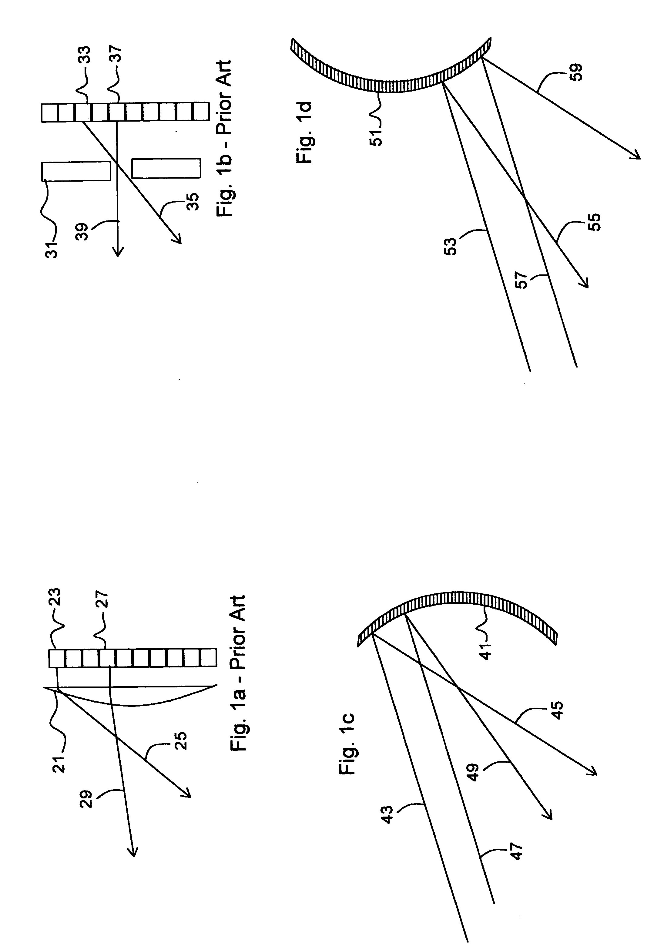
[0037]FIG. 1a Prior Art—depicts a top view of a lenticular lens 3D pixel. A 3D pixel lenticular lens 21 directs a light from a first lens sub pixel 23 to be a first lens directed perspective 25. The 3D pixel lenticular lens 21 directs a light from a second lens sub pixel 27 to be a second lens directed perspective 29. The 21 similarly directs light from multiple sub pixels into respective sections of user space. Depending upon a user's position, she will see one or two perspectives coming from the 21 lenticular and from thousands of similar 3D pixel lens lenticulars and thereby experience a 3D perspective. Similarly, according to multiple patent disclosures by the present application, the 29 can represent a first program and the 25 can represent a second program such that a first user will see a first program from the 29 and thousands of other sub-pixels while a second user sees a second program from the 25 and thousands of similar sub-pixels. The lenticular lens based system requir...

second embodiment

[0052]FIG. 6a illustrates a variable filter screen display in 2D mode. As described in FIG. 1b Prior Art, it is well known to provide a filter as a means to present 3D images. FIGS. 6a through 6c describe a filter method that comprises a variable filter width means to accommodate 3D video across a range of 3D resolutions. FIG. 6a describes a variable filter array 92 in an “on” state such that it is transparent throughout. The 92 can be comprised of one or more technologies that can be caused to change between transparent and opaque (or translucent) states such as an electro chromatic cell array or a liquid crystal cell array. All switches including a first switch in on state 90 are in the on state such that light from a pixel array including a first diffuse pixel 98 is able to travel through the surface of the 92 and into user space. This configuration is suitable for displaying 2D images since users across a wide range of viewing positions can see all of the pixels at full resoluti...


PUM


Abstract

In a first preferred embodiment, this invention provides a low cost means for reliably producing an auto-stereoscopic 3D front project display screen. The screen is engineered to distribute discrete portions of light across a range of discrete horizontal on and off axis viewing angles corresponding with perspective correct 3D images. The screen also distributes each of these pixels concurrently through a wide vertical range to enable users in vertical on axis and off axis viewing positions to see the pixels within their narrow horizontal field of vie yet through a wide vertical field of view. In a second embodiment, a 3D filter is provided that enables a display to automatically switch between displaying 3D media of a first 3D resolution and to display 3D media of a second 3D resolution. Both embodiments also enable multiple users to concurrently watch different programs on the same display at the same time.

Description

CROSS-REFERENCE TO RELATED APPLICATIONS [0001] This application is a continuation in part of the following patent applications by the present applicant; U.S. application Ser. No. 10 / 884,423 filed Jul. 03, 2004, and U.S. application Ser. No. 10 / 994,556 filed Nov. 22, 2004.BACKGROUND FIELD OF INVENTION [0002] Modern video display devices incorporate many technologies and methods for providing high quality video to users. Nearly every household in the United States has one or more video displays in the form of a television or a computer monitor. These devices generally use technologies such as Cathode Ray Tubes (CRT) tubes, FEDs, Liquid Crystal Displays (LCD), OLEDs, Plasma, Lasers, LCoS, Digital Micromirror Devices (DMD), front projection, rear projection, or direct view in one way or another. Large monitors offer the advantage of enabling many users to see the video monitor simultaneously as in a living room television application for example. Often video users do not want to view th...

Claims


Application Information

Patent Timeline
IPC IPC(8): G09G3/00G02B30/27H04N13/363
CPCG02B27/2214H04N13/0459H04N13/0404H04N13/305H04N13/363G02B30/27
Inventor ALDEN, RAY M.
Owner ALDEN RAY M
Why Eureka
Try Eureka