Loop frame detecting device and method for detecting loop frame

Inactive Publication Date: 2006-01-19
FUJITSU LTD
View PDF21 Cites 151 Cited by
  • Summary
  • Abstract
  • Description
  • Claims
  • Application Information

AI Technical Summary

Benefits of technology

[0022] It is an object of the present invention to solv

Problems solved by technology

On the other hand, for the purpose of such as the enhancement of the availability, it is often required to secure the redundancy of the intermediary device or the communication pathway, which causes inevitably a loop in the frame transmission.
However, the easiness induces incorrect connection, and consequently the network loop caused by incorrect connection.
For example, the failure is frequently caused by the non-intelligent hub that is commonly used at the end of the network.
However, in many cases the hub is not implemented any protocol for preventing the loop, such as STP.
Furthermore, in many cases a monitoring device in the network cannot even recognize the non-intelligent hub, because the hub cannot be externally accessed using telnet, Simple Network Management Protocol (SNMP), or the like.
Thus, the detection and the prevention of the failure are difficult.
Furthermore, even if the STP for preventing the loop is running on the hub, the network loop is also formed due to a failure occurred in the control system of the bridge, malfunction of the STP that failed to receive the BPDU packet, and so on.
When the loop failure occurs in the Layer 2 network, the broadcast storm caused by

Method used


Image

  • Loop frame detecting device and method for detecting loop frame
  • Loop frame detecting device and method for detecting loop frame
  • Loop frame detecting device and method for detecting loop frame

Examples


Embodiment Construction

[0049] Exemplary embodiments of a loop frame detecting device and a method for detecting loop frame according to the present invention will be explained in detail with reference to the accompanying drawings.

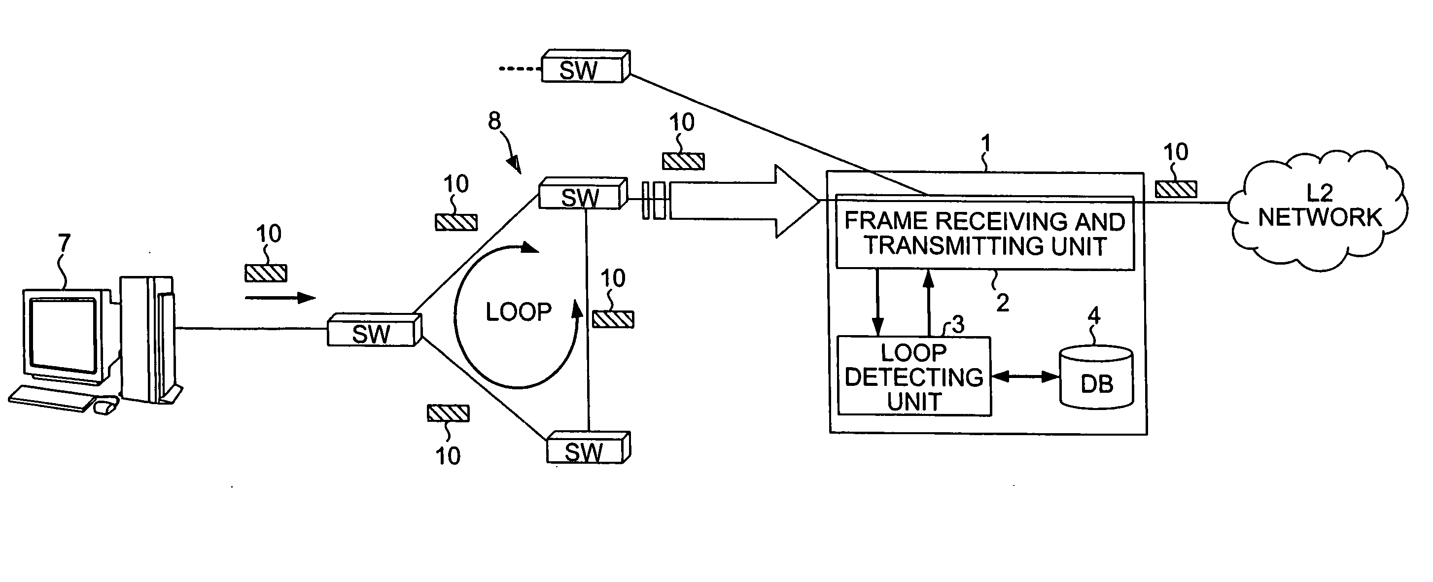
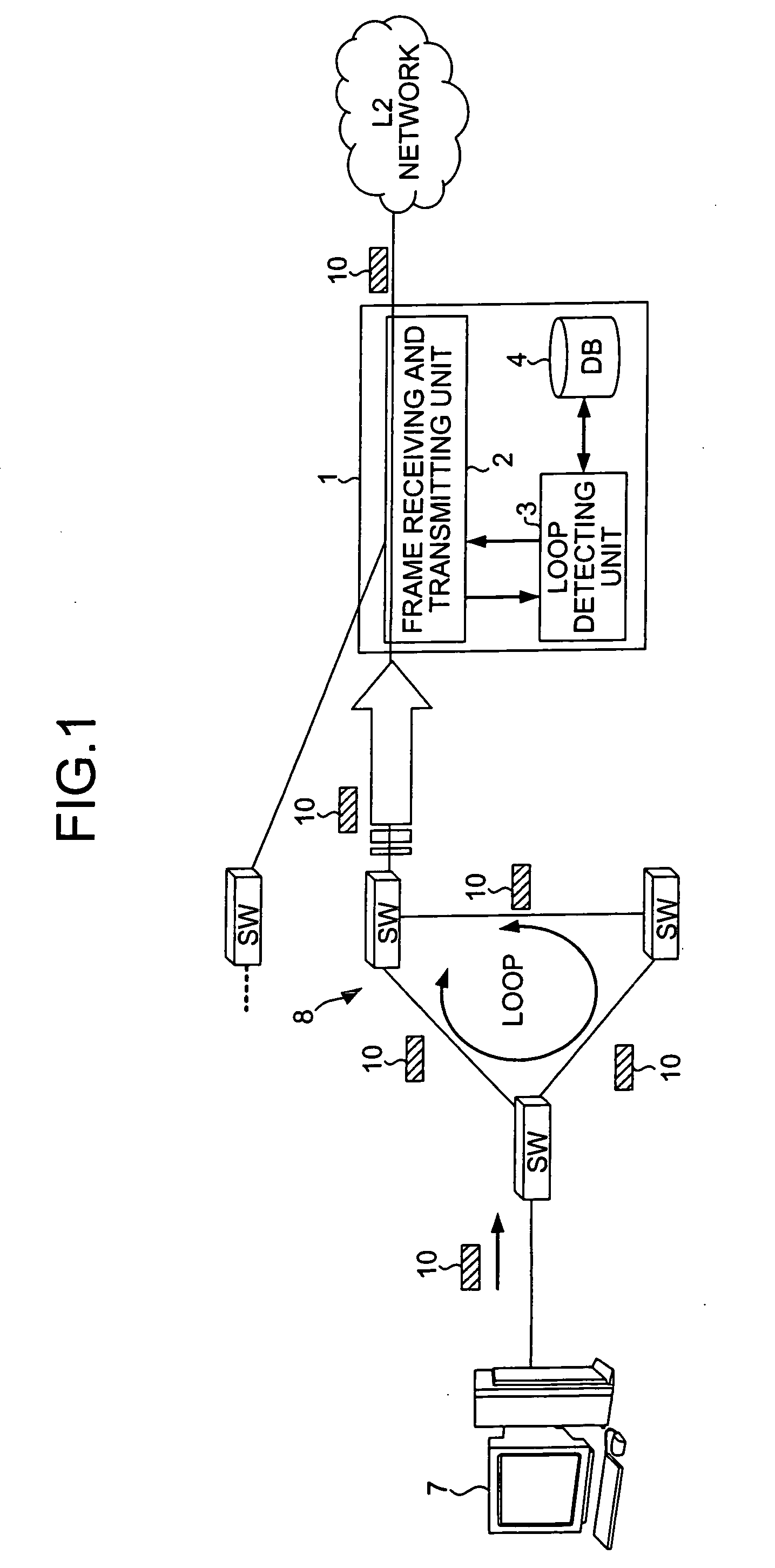
[0050]FIG. 1 is a simple schematic of loop frame detection using a loop frame detecting device according to the present invention. A frame is transmitted by a PC 7 or the like, and transferred over a network 8 via a network switch (SW) or the like. The loop frame detecting device 1 monitors the frame data itself or the hash value of the frame data. When detecting the number of an identical frame has exceeded a predetermined threshold, the loop frame detecting device 1 determines the frame as a loop frame and blocks or limits the traffic of the frame.

[0051] The loop frame detecting device 1 has a frame receiving and transmitting unit 2, a loop detecting unit 3, and a database 4. The frame receiving and transmitting unit 2 receives a frame data 10. The loop detecting unit 3 detec...


PUM


Abstract

A loop frame detecting devise includes a frame receiving and transmitting unit and a loop detecting unit. The frame receiving and transmitting unit receives and transmits the Layer 2 frame. The loop detecting unit monitors contents of the frame that is received or to be transmitted by the frame receiving and transmitting unit, determines whether the frame is a loop frame that circulates in the Layer 2 network, detects the loop frame, and minimizes a loop failure.

Description

CROSS-REFERENCE TO RELATED APPLICATIONS [0001] This application is based upon and claims the benefit of priority from the prior Japanese Patent Application No.2004-207517, filed on Jul. 14, 2004, the entire contents of which are incorporated herein by reference. BACKGROUND OF THE INVENTION [0002] 1) Field of the Invention [0003] The present invention relates to a technology for detecting a failure in a network, and preventing the failure or spreading of the failure. [0004] 2) Description of the Related Art [0005] Ethernet® is a typical configuration scheme of a LAN and falls into the second layer (hereinafter, “Layer 2” or “Data Link Layer”) network in the Open Systems Interconnection (OSI) reference model. The Institute of Electrical and Electronics Engineers (IEEE) defines the IEEE 802.3 standard as a standard specification for the network, and the information and telecommunications networks are widely used that comply with the standard or the extended standard of the standard (i....

Claims


Application Information

Patent Timeline
IPC IPC(8): G01R31/08H04L12/28
CPCH04L12/2602H04L12/462H04L45/48H04L45/00H04L45/18H04L43/00H04L45/76
Inventor MUTOH, RYOICHINISHI, TETSUYASUGITANI, KIICHI
Owner FUJITSU LTD
Why Eureka
Try Eureka