Variable dispersion compensator

a compensator and variable technology, applied in multiplex communication, instruments, optical elements, etc., can solve the problems of inability to easily produce, inferior gratings to dispersion compensation fibers in transmission characteristics, and various problems of conventional dispersion compensators, etc., to achieve low optical loss, reduce the effect of optical loss rippl

Inactive Publication Date: 2006-01-19
HITACHI METALS LTD
View PDF2 Cites 15 Cited by
  • Summary
  • Abstract
  • Description
  • Claims
  • Application Information

AI Technical Summary

Benefits of technology

[0015] The present invention makes it possible to obtain a variable dispersion compensator that offers a low-group-delay ripple, a large amount of variable dispersion, low optical loss, and low-loss ripple characteristics, over a wide band. This, in turn, allows simultaneous dispersion compensation of all optical signals during WDM optical transmission, and thus the extension of a transmission distance in a transmission system.
[0016] Simultaneous dispersion compensation is also possible for higher-order dispersions, and the use of the dispersion compensator according to the present invention allows the construction of a simplified, inexpensive optical communications system that has excellent transmission characteristics.

Problems solved by technology

These conventional dispersion compensators, however, have various problems.
Additionally, the dispersion compensation fiber produces a significant optical-fiber nonlinear effect and is thus likely to distort transmission waveforms, since it is usually small in mode field diameter.
It is therefore known that when used for dispersion compensation, these gratings are inferior to dispersion compensation fibers in transmission characteristics.
Also, there are the manufacturing-associated problems in that gratings large in the amount of dispersion or wide in wavelength band cannot be easily produced and in that gratings narrow in band require the stabilization of temperature and wavelength.
In addition, with a dispersion compensation fiber, the amount of dispersion cannot be continuously made variable in terms of principle, and this makes it difficult to realize the variable dispersion compensation that continuously changes the amount of dispersion according to the particular change in the amount of dispersion in the transmission line.
This scheme, however, poses problems associated with its practical use, because a uniform temperature gradient is difficult to obtain and thus because sufficient dispersion compensation performance cannot be obtained for reasons such as the occurrence of a ripple in wavelength dispersion.

Method used


Image

  • Variable dispersion compensator
  • Variable dispersion compensator
  • Variable dispersion compensator

Examples


first embodiment

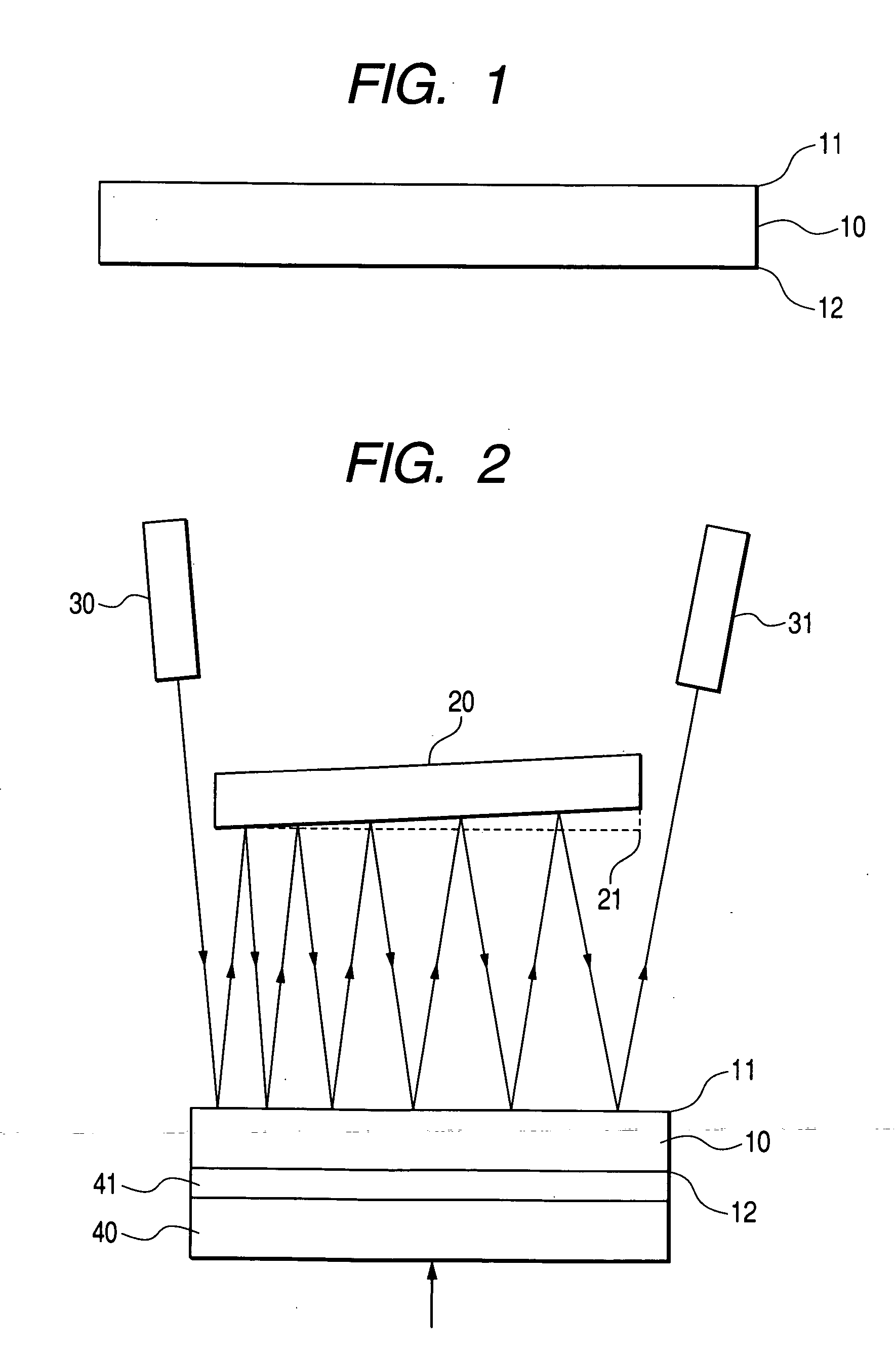
[0061] Embodiments of the present invention will be described in detail below using the accompanying drawings. First, an etalon is described. A structural view of the etalon is shown in FIG. 1. The etalon is a precisely parallelized planar plate 10 having upper and lower faces coated with reflecting films 11, 12. Metal films made of gold, silver, or other high-reflectance metallic materials, dielectric multi-layer films, or the like are used as the reflecting films. In particular, an etalon having ideally a reflectance of 100% on one face is called the GT etalon, which was named after Gires and Tournois, the proposers. In reality, however, it is difficult to obtain a reflectance of 100%, so the reflecting films may be allowed to have a reflectance of at least about 90%. In addition, the reflectance of one reflecting film does not need to be too high if the film is to be used for dispersion compensation, and as a more specific value will be shown hereinafter, the reflectance does not...

second embodiment

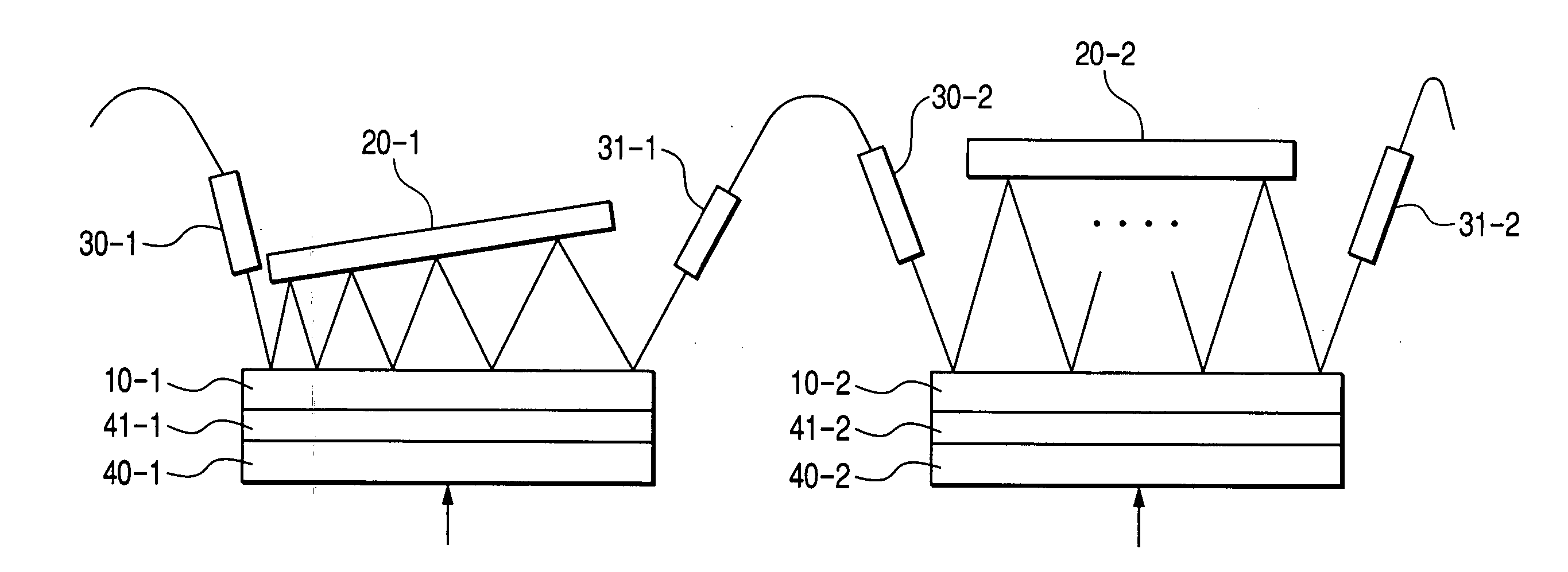
[0089] In another variable dispersion compensator of the present invention, light is obliquely admitted into an etalon and then reflected between the etalon and a mirror several times before being received by a collimator. Therefore, excessive loss and an excessive loss ripple are caused by each reflection from the etalon. This phenomenon will be described using figures and numerical expressions.

[0090] Main examples of experimentally obtained wavelength characteristics and loss characteristics are shown in FIGS. 34 and 35. Differences between both figures are due to differences in horizontal positions of collimators. In experiments, total reflection from the mirror was repeated four times (k=4) with mirror angle Δθ set to be almost equal to 0. It can be seen that although FIGS. 34 and 35 do not differ too greatly in dependence of dispersion on wavelength, these figures significantly differ in dependence of loss on wavelength. The dispersion characteristics shown in FIGS. 34 and 35 ...


PUM


Abstract

The present invention provides a dispersion compensator applicable to a WDM optical transmission system and featuring low loss, wideband usage, and minimum ripple. The dispersion compensator is constructed so that the light emitted from a collimator will be reflected from an etalon of a 100% single-side reflectance by arranging the etalon and a mirror in parallel or with a slight angle and then enter another collimator. Elements for achieving variable dispersion compensation by changing temperature using a heater, for example, are also provided. In addition, these dispersion compensating elements are provided in multi-stage form and the angle of the mirror and the reflectance of the etalon are optimized. Thus, it becomes possible to realize a dispersion compensator applicable to a WDM optical transmission system and featuring low loss, wideband usage, and minimum ripple.

Description

CLAIM OF PRIORITY [0001] The present application claims priority from Japanese applications JP 2004-207049, filed on Jul. 14, 2004, 2005-037623, filed on Feb. 15, 2005, and 2005-036299, filed on Feb. 14, 2005, the contents of which are hereby incorporated by reference into this application. BACKGROUND OF THE INVENTION [0002] 1. Field of the Invention [0003] The present invention relates to variable dispersion compensators, and more particularly, to optical dispersion compensators suitable for application to the optical transmission systems using optical fibers and the systems that employ an optical transmission scheme based on wavelength division multiplexing. [0004] 2. Description of the Related Art [0005] Research and development activities on the long-distance optical transmission systems that use optical amplifiers as repeaters, have been actively performed in recent years. Enhancing capacity by WDM (Wavelength Division Multiplexing) intended for division-multiplexing plural opt...

Claims


Application Information

Patent Timeline
Patent Type & Authority Applications(United States)
IPC IPC(8): G02B6/26
CPCG02B6/29358G02B6/29395G02B6/29394
Inventor SUGAWARA, TOSHIKIMAKIO, SATOSHI
Owner HITACHI METALS LTD
Why Eureka
Try Eureka